|
ApexJr Ribbon Tweeter |
||||||||||||||||
|
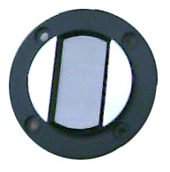
Steve at ApexJr has come across some ribbon tweeters he is selling for $5 each. I have a set of these running in a set of mini-monitors with just a 3.3 mF cap in series (and an inductor on the woofer). They took a couple days to loosen up, but as they did, the more I listened to them the more amazed I was at how good these tweeters are. I am using them with the bezel & grill removed. From the efficiency rating of the woofer, they are in the 88-90 dB 1 watt range. The magnet structure must be inherently shielded since i can bring the ribbon element within a couple inches of my monitor before i get any effect. I get no effect when it is right up against the back or side of my monitor. The bezel & grill are fairly easily removed by scraping off the melted part of six tabs on the back. Getting the ribbon elemnt out of the plastic faceplate is somewhat more challenging as it is glued in. If someone gets more measurements I'll happily post them. Just e-me. Initial reaction: If anyone wants a really decent sounding tweeter that you can use in an AV setup for almost no cost, this is a good one. More Info:
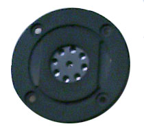
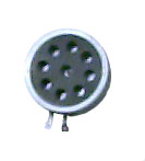
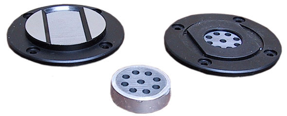
CARTRIDGE CONSTRUCTION: Two ceramic magnets pressed together so that 'positive' poles face and magnetically oppose each other and squeeze the diaphragm sandwich. Magnets are each about 4 mm thick and 38 mm in diameter. The forward facing magnet has nine 5 mm holes through it to port the sound. The rear magnet has no holes defining a monopole construction. (The rear magnet has a paper cover to protect it from physical abuse.) The front hole pattern has one at the center and eight forming a circle of 22 mm diameter c-to-c. MOUNTING FLANGE
OR BEZEL: IMPEDANCE MEASUREMENT:
impedance chart (measured Re=7 W) measured by Andrew Zeitoun using Speaker Workshop
|
||||||||||||||||
|
[ Back to the TL Speaker Page ] |
||||||||||||||||