|
The Seraphim
Spiral Transmission
Line Speaker System
22_10_04
by John David Duke Jr.
<note:
most pictures have a larger one linked to the thumbnail>
"And the foundations
of the thresholds shook at the voice of the seraph who called, and the temple was
filled with smoke." -- Isaiah 6:1-4
|
Editors Note:
one thing David doesn't mention in the article is that this project was meant to
provide nursery room tunes for the soon to be born Thomas (seen below). I'd like
to personally thank Thomas for inspiring such an awesome & imaginative project.

|

|
Introduction
It is my pleasure to present to the public my spiral-shaped transmission line
system. I call them The Seraphim because Isaiah, in his great vision of the heavenly
throne-room, saw fiery beings who stood above the Lord; yet they darted back and
forth, and they shouted to one another so earnestly that the door posts were shaking,
much like what happens when a properly amplified and crafted set of drivers and speakers
will do when they are commanded to speak.
I must speak forthrightly: these speakers are only partially the result of mathematical
design and otherwise solid sound-reinforcement science. Yet, even though this design
is the result of wishful thinking, there is a fair measure of design and science
in the several aspect of these speakers. That, and they sound awesome.
I will now turn to those various aspects in a given order
Acknowledgements:
First, Ill mention only a few people, but I wanted to do it immediately because
I could never have accomplished this without some serious help. Martin King e-mailed
with me when I had questions, stupid ones, about his marvelous T-Line Mathcad worksheets. My wife is infinitely
patient; for whatever reason, I dont know. diyAudio Forum>Loudspeakers was
a primary source, including such knowledgeable and helpful persons -- patient, too,
with my stupid questions -- as David Dlugos (Planet10), Peter D. OConnell (Kelticwizard),
Andrew Faust (faustian bargin), Sch3mat1c, Steve, and a few others Im forgetting.
In addition, Bob Brines website is pretty good.
The Design
Tetrahedron: I inherited a pair of regular-tetrahedronal shaped
speakers (4 baffles cut as equilateral triangles). In the course of history they
were harmed in such a way that they needed repair. The design function of the tetrahedron
is to remove any parallel surfaces, which is advantageous. However, apart from that
feature, the actual speakers in hand were poorly designed. They were very small and,
therefore, not properly tuned for reasonable response, really. They were sealed,
yet there was no internal damping, which caused resonance in a bad way.
I wanted to keep the tetrahedronal idea, but a tetrahedron is not a good way to capture
the necessary volume for a two-way speaker system that might have a decent response.
A 1.5 cu.ft. box of this shape is HUGE! Porting was also an issue since the stereo
spectrum was at stake, and the angling, in many respects, was a difficult problem
to solve. Baffling was yet another problem; diffraction models showed that any triangle-shaped
baffle that was not equilateral was going to adversely affect the driver response.
I was still determined to keep the principle of a tetrahedron, that is,
waves are bounced at all sorts of angles to reduce standing waves in a box.
nOrh: A few years ago I bought a pair of nOrh 4.0s. They are awesome. There
are no parallel surfaces, and the bass response for a pair of 5.5" drivers,
whatever quality they are, is astounding. The clarity and detail -- I knew that normal
woofers could produce for me some serious bass detail without having to sacrifice
midrange frequencies, and, crossed-over to a decent tweeter, high frequencies. The
shape (the Thai Longdrum), however, was not something I could construct without actually
stealing the idea, and thats theft.
Transmission Line: Well, David Dlugos has an interesting website called t-linespeakers. There you will find several
actual PVC pipes that masquerade as full range speakers built by one Robert Sampson.
"No way!" I said to myself. Yes, way. A pvc pipe is tuned to the quarter
wavelength of the Fs of your driver, then tapered a little, then the living
daylights are stuffed into it until it sounds right. "Surely theres more to
it than that"" I said, a born skeptic.
In fact, there is and there isnt. Transmission lines really do work like that, and
as I understand, they sound great if that is, special attention is paid to the resonant
frequency. Once you stuff the line, the resonant frequency seems to change. You can
search the web for all sorts of details concerning this. Most important of all the
internet resources is Martin J. Kings quarter-wave
website. On
it he has a mathematical model completely worked out that resolves this perceived
resonant frequency change problem which comes about when you build any shape of T-Line.
 |
Miscellaneous: Im
not very good at woodworking for several reasons: I dont have very many tools, I
swear a lot (which is undesirable), its cold outside (the winter of 2003 was Canada-like
in Saint Louis!), I live in an apartment.
I liked the idea of making a speaker out of PVC pipe. It seems cool.
I bought a set of drivers with the crossovers already designed by Madisound to
replace the ones in the inherited tetrahedronal speaker (see above). So I had to
do something. |
Summary:
- A tetrahedron is a
desirable shape for a box, but would require too great a size for too little a gain.
- The nOrh design is
almost perfect, but the idea is someone elses.
- Transmission line
designs are easily designed with great results, but PVC pipes resonate too
well.
- I dont work well
with wood.
Conclusion: I will design a speaker enclosure which keeps an
eye toward all the desirables of the above, but avoids the undesirables. That design
is a PVC pipe which spirals downward from the source. It is a transmission line.
The Spiral Shape in Concept and in Math. Kings mathematical worksheets are
essential in order to design a proper transmission line. I used them to model a straight
pipe that had its driver offset a bit. One of the immediate weaknesses of my design
is the size of the throat. Such a small opening which maintains a ratio of 1 Sd
to 1 Sd is not going to smooth out the driver response very well, nor
is it going to be enough room to support the bass frequencies I could get
with these drivers (see below). Nevertheless, I kept this model for reasons I will
discuss below. Furthermore, the ripple was limited to +/-2dB, so I wasnt terrified.
In addition, the accuracy of the modeling worksheets falls off somewhere above 2kHz.
Theyre designed to model midbass to bass response.
When a pipe bends, it forms a shape, at the bend, reminscent of a pyramid. When
the pipe bends to the side and also downward, the shape formed at the bend is reminiscent
of an oblique tetrahedron. I am quite aware of the fact that this is impossible
to model mathematically with respect to calculating the T/S specifications. However,
Im confident that neither does it invoke the problem of a fold (cf. a traditional
folded TQWT), nor does it return us to the problem of constructing a tetrahedronal-shaped
box. In fact, you could say that the shape formed inside the pipe is a continuously
progressing sphere, if you can think of yourself actually passing through a spiral.
In any case, the enclosure is no longer circular, but some sort of oblong sphere.
When I say progressing, Im talking about measuring the inside of a curve that not
only progresses to one side but also progresses downward. Its not just a diagonal,
either, which would be uni-directional. The point is that the inside of a pipe that
is spiraling is multi-directional. Think: infinity. You never get to the inside of
a curve (fractal theory), and here we have an infinitely varying, yet consistently
varying, curve with respect to direction.
In my estimation, it looks cool first, then sounds good, not the other way around.
On the other hand, the sphere, especially an oblong-shaped sphere (cf. domes, eggs,
etc.) is renowned for its architectural value. In addition, waves are exerting
force progressively irregularly on the pipe until it is forced out the port (this
is demonstrable in particle theory!). I believe that this progressive shape
caused by spiraling pipe and the progressively changing force exerted will change
significantly the resonating qualities (or accidents) of the pipe. I also believe
that the shape of the enclosure affects the standing wave(s) in a predictable way.
Will this have a positive or negative effect on the pipe resonances. Well see!
Construction
The Math: I had a pair of Vifa P17-WG-00-06 drivers, and a pair
of Vifa D27-TG-00-06 tweeters. Madisound built a standard crossover for them
when I purchased them. Martin Kings mathcad worksheets determined a reasonable enclosure
based on the T/S parameters of the speakers. I used almost all the variations offered
in order to model an ideal enclosure, and then was determined to build one that was
less ideal because the ideal one was much too unwieldy.
Even so, there were still manifold problems in the construction of such a beast.
Allow me to chronicle my travails, because the series of failures are most often
attributed by my station in life, not the actual foolishness of the ideas.
PVC Elbows: 6-inch PVC is exponentially more expensive, for some reason, than
its 2 and 4-inch brethren. The elbows are particularly expensive. Schedule
40 90s cost over $25 USD per, and sewer grade 90s were around $10. Twelve elbows,
in addition to two tees ($25-$10 per), were required for the project, so the cost
was prohibitive.
PVC pipe: My next solution was to bend the PVC pipe. I bought two tees and
twelve feet of sewer grade pipe ($42 total). There are several methods known to bend
smaller diameter PVC pipes, but every method failed with the 6-inch diameter. In
fact, 6-inch PVC pipe will not bend anywhere near the angle that I needed. Generally
speaking, this size of pipe will not heat evenly with anything less than professional
plumbers tools; indeed, probably nothing less than a contractors tools. And no
contractors tool could possibly bend 6-inch PVC pipe 540° over the course of
60 inches.
When I finally realized the impossibility of achieving my goal of bending the pipe,
I despaired. I had expended a considerable amount of time and energy, with negative
results. At that point, I simply posted my idea on the diyAudio forum to see if someone would take
the idea and build it himself. I just wanted to know how it might work.
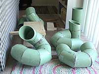
Cut PVC pipe: Well, once I posted it, there was a measure of interest beyond
what I imagined. I had thought it was a cockamamie idea, but several people took
special interest in it, suggesting that I cut the PVC at angles in order to form
a spiral. The problem with this was that I had no tools to speak of, and, as mentioned
above, I wasnt very good with tools anyway. As a further complication, I have absolutely
no working skill with mathematics in geometry, and I have a hard time conceiving
of the world in shapes and numbers altogether. That was no deterrence. The boys at
the forum walked me through every single imaginable detail in modeling a spiral that
I could cut with a handsaw (normal power tools are ineffective against a 6-inch PVC
pipe; believe me), brought to mind several practical realities in cutting PVC pipe
at an angle, and even helped me design a jig. The final numbers are given in several
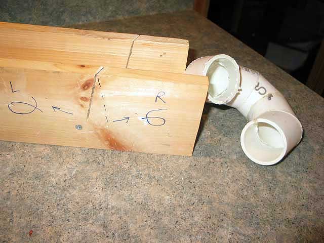
forms here:
Segment specifications per enclosure:
14 pieces as follows: 11 "main" pieces, one port piece, one tee mount piece,
one tee.
All the pieces were to be cut at a 22.5° angle. The main pieces were to be cut
at that angle, but at an 11° turn relative to the last cut.
This 11° turn provides the "rise" in order to make the octagon-shape
into a 3-dimensional spiral. For one enclosure, we determined that the turn would
be positive, and for the other, negative (I actually thought of this one myself!).
Thus, the 6 3/8" outside diameter PVC pipe measured 7 1/8" on the "long"
side, and 1 7/8" on the "short" side. Once the 11° turn is introduced,
there is no long or short, but twisty-turny.
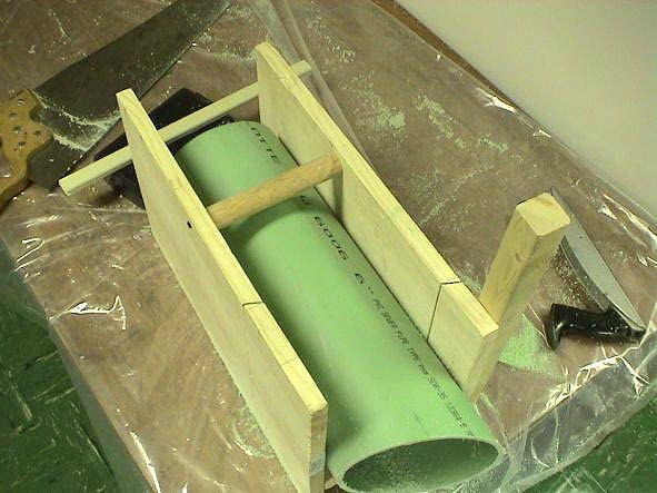
I devised a method for doing this in short order. I sawed a piece of wood to be exactly
as wide as the diameter of the PVC pipe and about a foot long. I then sawed a pair
of 10 inch high and 18 inch long pieces of wood to serve as walls for the jig. The
length of the walls also ensured that plenty of pipe was in the jig in order to prevent
any slipping, turning or other accidents while sawing the angle. I attached the walls,
then measured, on the inside of the walls, a distance 2 5/8". That was my 22.5°
angle. Then I used a handsaw to cut, to the inside of the marks, my jigs
saw guides.
After that, I took a decent gauged string and measured its length around the circumference
of the pipe. I marked the string at both places where the string met after pulling
it to a certain tension. I folded that length in half, marking it. That served as
my 180° turn so that I could measure the "long" side of the pipe. I
folded it half again from that point, marking it. That served as my 90° point,
which I would use to measure against my "x" (keep reading). I folded a
few more times until I was down to only 5/8". That served as my 11° mark,
which I would use to turn my pipe. Before I proceed, heres a chart form for the
lengths of pipe:
| 66 inches total pipe length |
Long Side
|
Short Side
|
|
| Port End Piece |
7 1/8"
|
unimportant
|
| Main Piece |
7 1/8"
|
1 7/8"
|
| Tee Mount Piece |
unimportant
|
3"
|
| Tee |
3" mount
|
6" internal length
|
|
Procedure: I placed a French dictionary in the bottom of my jig. This served
to raise the pipe a few inches off the cutting surface itself in order to cut almost
completely through the pipe; otherwise, the saw would hit the bottom, and the walls
would be unstable if they were cut so close to the bottom of the jig. I also used
a block of wood or something for the end of the pipe extending from the jig so that
I wouldnt end up cutting at some indeterminate third angle in addition to the other
two. I then measured 7 1/8"" from the end of one of the uncut pieces of
pipe (they came in two 6-foot lengths). I measured 90° from that mark. I placed
the 7 1/8" mark directly in the "long" jig-guide, turning the pipe
until I determined that the saw would cut at a 90° angle with respect to the
7 1/8" mark. This was very important to maintain the integrity of the 11°
rise when I put the pieces together later on. The 90° mark was unimportant with
this particular piece, but I verified that I could saw through the "x"
on the 7 1/8" mark. And I hit it dead-on 23 out of 24 times. The only failure
I had was when the jig broke as I was in the process of sawing.
After I sawed my Port End Piece, I got my string out. I wound it around the
pipe, found my two end marks, placed them carefully over the half an "x"
that was left from my perfect cut, then marked the 180° point of the pipe from
that point. That mark was now veritably on the same plane and line with the long
point of the pipe. I measured 7 1/8" from the end of the pipe on that plane
and line and marked it. Then I used my string again to mark the 11° point (+
or depending on the enclosure). I marked that with the next "x" and a
thin line for later reference. I used my string yet again to mark the 90° point
from the 11° "x", made a thick line for later reference, labelled my
piece (e.g., segment 9) on the 90° line and had an arrow pointing to the near
end of the pipe (toward the last cut, not toward the virgin part of the pipe), all
for later reference. I arranged the pipe in the jig so that the 90° mark was,
indeed, pointing completely perpendicular to the jig walls. I sawed, as best I could
through the 90° mark, repeated, and continued till I thought I would drop dead
from exhaustion. My kingdom for a gigantic rigid bandsaw!
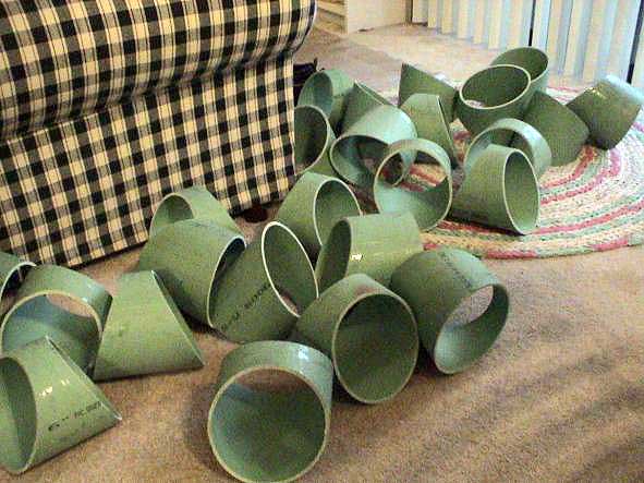
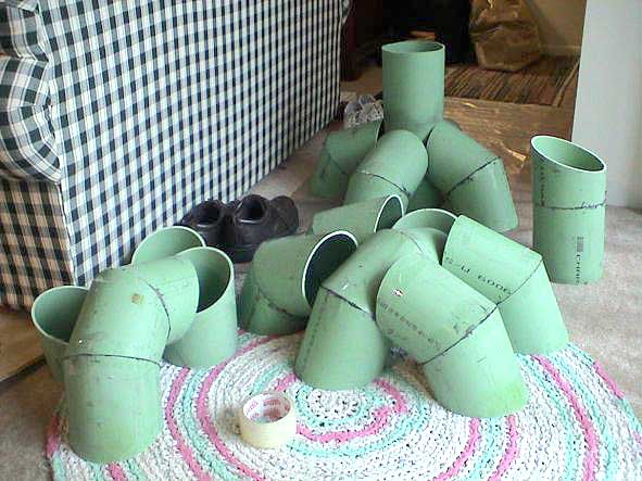
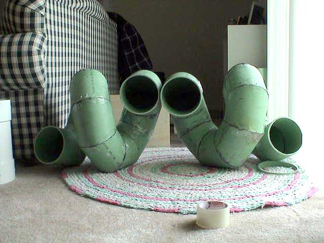
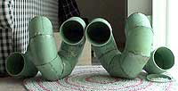
|

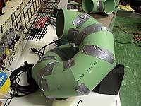
1st prototype
|
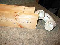
2nd prototype
|
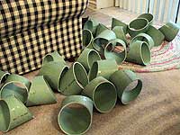
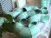
the real thing (unassembled)
|
The Human Element:
The fact of the matter is, aside from the time the jig broke, the human element was
largely negligible in the end. The one significant element was that the pipe wasnt
actually round. At certain points it was oblong. Some of the segments, therefore,
didnt quite fit flush during assembly. I honestly thought Id have more to write
here, but thats it. |
|
| |
|
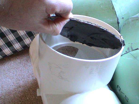
| Assembly: Unfortunately, as Ive mentioned before, winter in St. Louis was
persistently cold, so my workshop was not inhabitable. Therefore, any sort of PVC
cement was out of the question. This was not good. As a workaround, it was suggested
to me to buy some plumbers epoxy, and the particular brand that was recommended
to me was PC-7. This epoxy comes in two cans, a part A and a part B. You simply mix
a spoonful of each on a palette and apply a thin layer to each surface you wish to
adhere, then you set the joint somehow, and its serviceable in less than 24 hours. |
| |
|
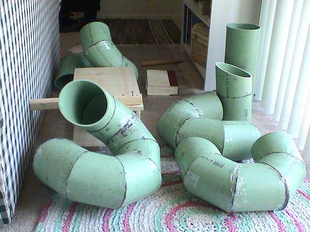
I began each enclosure from either end, that is, I started with the port piece on
the one enclosure, and with the closed-end piece on the other enclosure. I did this
to keep myself from "cheating," or looking over my own shoulder. This way
I had to trust my own marks rather than my eyes. The assembly proceeded in four distinct
phases.
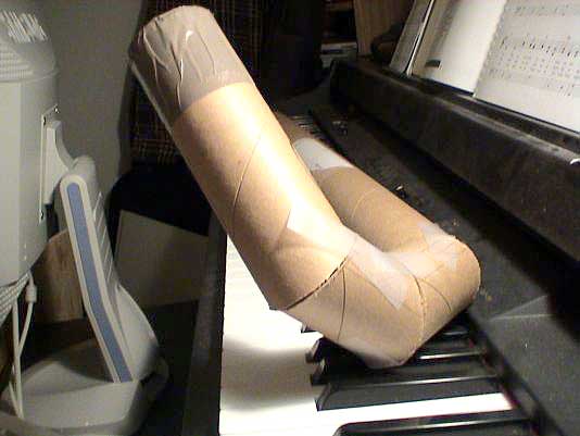
1) Phase One: I epoxied two segments of each enclosure at a time. For example,
I had numbered the segments from 1 to 13. I epoxied segments 1 and 2, 3 and 4, 5
and 6, and so on, until I got to the odd piece at the end. Then I made a "triple
segment.. Each joint I set with generous amounts of packing tape, then I set them
at angles least susceptible to gravity, and had a long winters nap. This took an
hour or two per enclosure. Thus, I was left with 6 segments per enclosure.
2) Phase Two: I epoxied the 6 double-segments till there were three total
segments. I let dry overnight. This took a total of about an hour. Again, I set each
joint with packing tape. At this point, I found a joint which had not sealed properly.
Surprise! It was the segment which had been malformed by the jig-accident early on
while sawing the pipe. I patched it and verified the integrity of all the other joints.
3) Phase Three: I epoxied two of the three remaining segments per enclosure.
4) Phase Four: I epoxied the last remaining segment, and the main body of
the speaker enclosures were done.
I tested the integrity and strength of the enclosures by dropping them and kicking
them. Sure enough, one of the port pieces snapped off, the very first joint I had
epoxied. After testing some more, I was satisfied that it must have been a rookie
mistake on that one joint, so I used a utility knife to scrape the epoxy off, and
re-epoxied.
Youve got to understand that this cost me an entire day to work on them. In fact,
it was a weekend day, which I have the most time to work on projects. This delay
effectively cost me a week. I was not happy, but I remained patient. |
|
| |
|
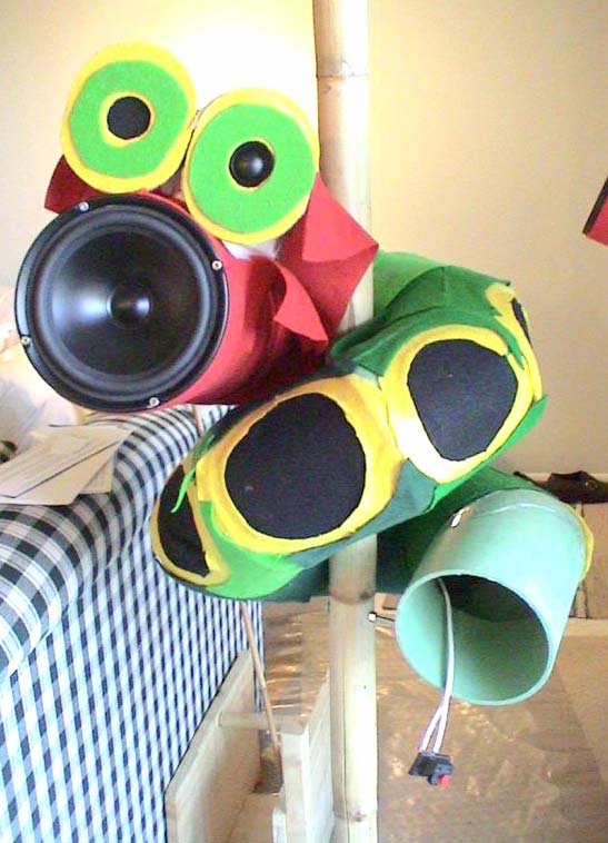
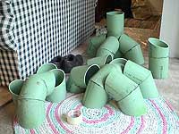
| Damping. These things rang like a bell when struck, so I could only imagine
that they would resonate like crazy. The segmented nature of the pipe did not
save me from that particular problem as I thought it would. However, the epoxy
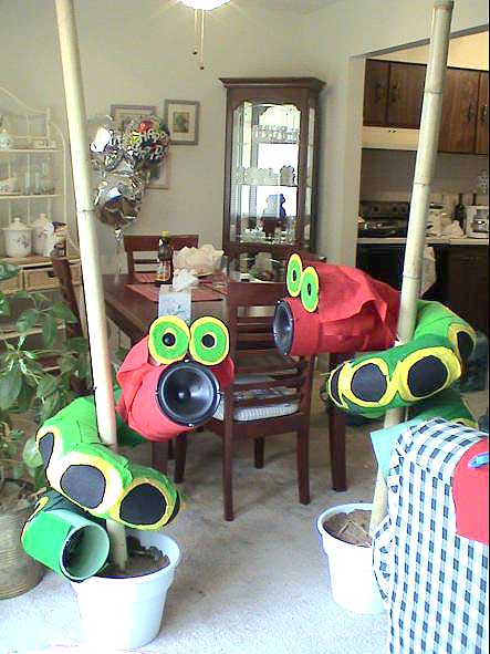
has certainly done its job. Upon a suggestion, I bought armloads of craft-felt squares,
mostly shades of green, and proceeded to decorate the the entire outside of the enclosures
to resemble The Very Hungry Caterpillar by Eric Carle. I met with a certain,
though limited, success. I acquired a giant bottle of Elmers Glue-all glue and absolutely
drenched the entire enclosure with gobs of glue, then stuck odd felt shapes to it
till the job was done. Now the enclosure does not ring, not at all. |
| |
|
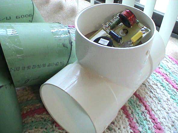
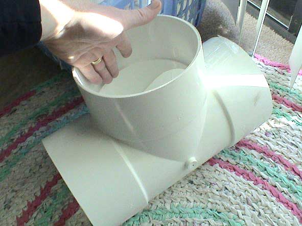
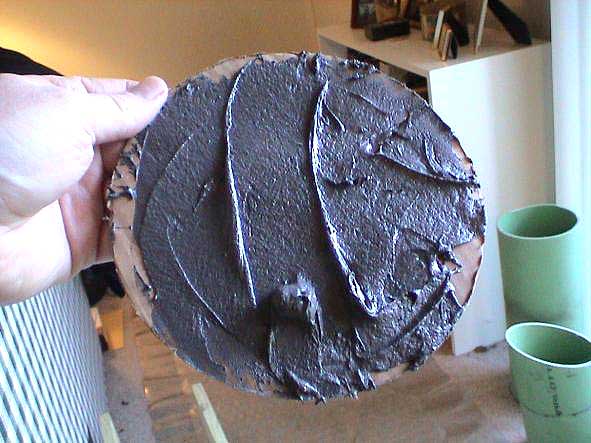
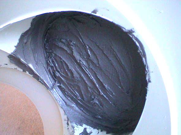
| Preparing the Mount: The tee had to be sealed somehow. I had designed the
enclosure so that the driver would fire straight down the pipe. That means that the
tee would then have a "top," i.e., the "stem" of the tee shape.
Conveniently, this region of the tee was just large enough to hold the crossover
components. However, if I used a big piece of wood, Id lose just enough volume of
that space to prevent the crossover from fitting properly. In order to solve this
problem without having to make some sort of wooden plug, I took a piece of cardboard,
cut to the right size and shape, covered the bottom of it in epoxy, then inserted
it into the tee. This, in effect, sealed the enclosure while maintaining the necessary
space for the crossover. In order to strengthen and thicken the seal, I applied a
few coats of epoxy as time wore on. Then I drilled two small holes to run the wiring
from the crossover to the woofer and to the enclosure port. Those holes I sealed
with poster-putty. That makes them temporary, yet snug. |

|
Mounting the Drivers: This was supposed to have been a cakewalk, but it wasnt.
The Vifa P17-WG-00-06 drivers initially fit like a glove over the mounting surface
of the PVC tee. That proved to be a minor problem in the end. I simply covered the
surface of the tee in red-colored felt, then left extra felt at the mounting end
in order to serve as a gasket. I drilled holes in the tee for screws, then forced
the driver onto the tee. After some struggling and a few mild oaths, the driver popped
right on, and I secured them with screws.
The Vifa D27-TG-00-06 tweeters were a different problem, though. How on earth was
I going to keep these things looking like a loveable worm-creature from a picture
book if it had a hideous mutation, having only one eye"!. Then it came to me
in a flash. One of the few things I thought of before it was suggested to me was
to construct a fake tweeter, or, in practice, to construct a "real" eye
and alter the appearance of the tweeter to resemble the eye. I cut out a few oblong
shaped pieces of cardboard for eyes, and a few oblong pieces of felt to decorate
them and the tweeters, along with a few slivers of cardboard to attach to the tweeters
in order to make them look oblong. It was perfect.
Now, there came the added problem of mounting the tweeter on a spherical
surface. I measured and marked on the pipe the place where I wanted to have the
tweeter mounted. Then I constructed a "hat" out of heavier-duty cardboard
which would cover the top of the tee and serve as a square mount for the eyes. I
cut a hole for the rear of the tweeter, wired it up, and mounted everything with
hot glue. Now my creature has eyes, one of which is a tweeter on the same plane and
angle with the voice coil of the woofer.
One thing I should note: the tee is constructed, I guess, in halves. There was a
nice seam running directly down the center of the entire thing, a very helpful reference
mark when trying to line up the woofer and tweeter components.
|
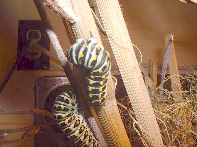
|
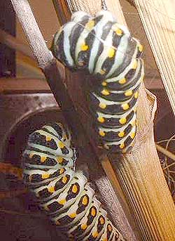
the inspiration
|
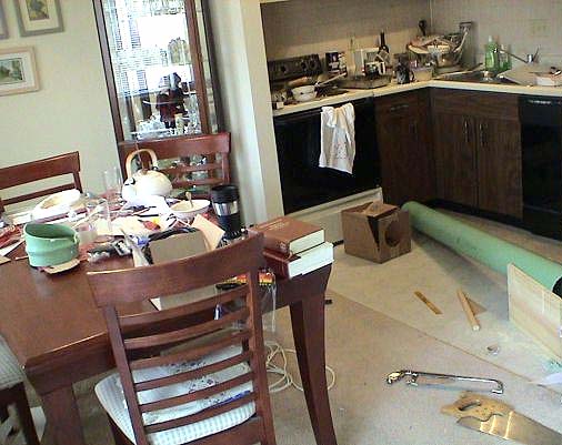
Mounting the Enclosures: Garden Ridge had a Spring inventory clearance sale,
so I bought a couple of 6-foot high 2-inch bamboo poles, some plastic greenery, some
sand and two buckets. I set the bamboo poles in the sand (which, of course, had been
poured in the buckets), drilled a hole large enough for a fair sized bolt, passed
the bolt through the hole, fastened the bolt with a nut, then set the enclosures
on the bolt. The pole is just wide enough that I achieved a snug fit. The weight
of the driver-end of the enclosure causes enough torque, I suppose, that there is
sufficient force on either side of the enclosure to keep it from moving during playback.
After I placed the enclosures, I poured a nice amount of Plaster of Paris on top
of the sand, and the anchors are as solid as can be, yet temporary for any future
moving.
Sound
These things sound surprisingly good. Now, I always believed that they would
sound good, but they are better-sounding than I let myself believe possible. Ill
add an addendum after Ive had time to break them in.
May 27, 2003
John David Duke Jr
St. Louis, Missouri, USA
|