|
Paul is a noted electronics designer and
responsible for much of the Bottlehead
line. This is derived from a post on the Full-Range Driver Forum
Written by Paul Joppa at 20 Apr 2004
A little while ago, Jon Ver Halen asked me to look into a line level equalizer that
would provide the same equalization as the popular LR and LCR speaker level filters
that are often used for single-driver speakers. Bass reflex and to some extent TQWT
designs seem to be especially common applications. This started as a commercial project,
but it turned out to be so simple that I thought it would be better to just put it
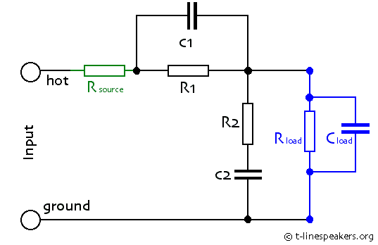
in the public domain. Here is the result:

In the midband the gain is reduced to R2/R1+R2,
and is -6dB when R1 = R2. C2 provides the low frequency
boost by restoring the gain to unity at the lowest frequencies. C1 is
optional, and provides some treble boost (restores the gain to unity at the highest
frequencies).
The LF time constants are R2*C2 and (R1+R2)*C2.
The HF time constants are R1*C1 and (R1 || R2)*C1,
where R1 || R2 means R1 in parallel with R2.
Frequency is 1/(2*pi*time constant).
To make the calculations simpler, I assumed that the source impedance (Rsource)
is much lower than R1 or R2, the load impedance (Rload)
is much higher than R1 or R2, and the capacitance of the load
(Cload) is much smaller than C1, which is itself much smaller
than C2.
In practice, as long as Rsource is less than half of R1 ||
R2, and Rload is more than twice R1 + R2,
the response will be within a dB of the predicted values. The greatest practical
difficulty is with Cload. It must be less than 10% of C1 in
order for it to affect the performance by less than 1dB. Most of its effect is above
the HF corner frequencies, so it might be reasonable to use a Cload as
high as 20% of C1. If C1 is not used, then the only limitation
is the (R1 || R2)*Cload time constant, which will
cause a treble rolloff.
As an example, I determined parameters for two implementations (one active, one passive)
to match Martin King's revised speaker level circuit, shown at:
http://www.quarter-wave.com/Project04/Project04.html
His speaker-level circuit has approximately 5.2dB midband cut, with low frequency
corners at 220 and 400Hz and high frequency corners at 10kHz and 18kHz.
The active implementation assumes a tube gain stage to make up the 5dB loss, and
a direct-coupled cathode follower so that Cload is very small and Rload
is essentially infinite. Here are the values:
Rsource = 15k
R1 = 220k
C1 = 68pF
R2 = 270k
C2 = 0.0015uF
Cload = 10pF
I compared this using the PSpice circuit simulation program to a model of King's
circuit, assuming a constant 8 ohm speaker impedance (roughly what he measured, above
200Hz). The match is good, except this circuit is 1dB down at 20kHz due to the 10pF
input capacitance of the cathode follower.
For a passive implementation between preamp and power amp, the Cload would
be larger. Most tube amps have around 100pF input capacitance, and the cable will
have more. A frequently used number is 1000pF for long cables, but with short cables
of 3 feet or less, a Cload of 200pF might be achievable. Then you could
use the following values:
Rsource < 2k ohm
R1 = 10k
C1 = 1500pF
R2 = 12k
C2 = 0.033uF
Rload > 50k
Cload = 200pF
A minimum load of 12k is presented to the source, which is on the low side but achievable
with most gear; in the midband the load is 22k.
For experimenters, a useful modification would be make R1 a variable resistance,
or replace both R1 and R2 with a linear taper potentiometer.
This way the magnitude of the boost can be adjusted, to compensate for room acoustics
for instance.
I hope this is useful to the community.
(Rod
Elliot's simpilar scheme)
|
