|
|
|||||||||||||||||||||||||||||||||||||||||||||||||||||||||||||||||||||||||||||||||||||||||||||||||||||||||||||
| For many decades, quarter-wave
loudspeakers have been designed by trial and error. Inefficiency and mid-bass ripple
were unpredictable complications of quarter-wave design. Another problem was mid-bass
output from the aperture. I set out to build a quarter-wave enclosure with the most
low frequency output possible. I hoped to minimize mid-bass peaks and troughs often
associated with quarter-wave enclosures. I wanted to do this without damping the
enclosure with wool or polyester stuffing. This was ambitious. The Rhinos worked
well as subwoofers. They had their shortcomings but I hope to improve the mid-bass
with my next project. By understanding unstuffed enclosures, I expect to build predictable
quarter-wave systems. I am convinced well-designed quarter-wave systems flow from Thiele-Small parameters. I checked many sources. There has been nothing in the literature associating cabinet design to fs, Qts and Vas. I searched past issues of Speaker Builder and JAES along with classic texts like Sound and Acoustics. From my reading, I developed a Thiele-Small quarter-wave design system. I constructed a quarter-wave cabinet matched one of the better drivers available. I could build a cabinet for maximum efficiency or for flat impedance (sometimes called maximum sensitivity). I will have a complete Thiele-Small design system organized soon, thanks in part to this project. This article describes two high-efficiency quarter-wave subwoofers. I named these test models the "Rhinos" because they are very powerful horns. Because I wanted to cover the lowest octave a powerfully as possible, I wanted to use a 12", 15" or 18" driver. The only large driver that met my predicted requirements was the Pyle FA124. It is an exceptional driver; retail price - $115. Pyle designed this for automotive applications. They did not know it at the time but this is the best large driver for quarter-wave systems. I used an Audio Control sub-harmonic restoration system with crossover, so I wanted a loudspeaker that could go very, very low. A quarter-wave system with this driver should have substantial output one octave below fs. I do not know of another design that could match this. Qts is high at 0.774 and Vas is low for a 12-inch driver at 5530 in3 (90.6 liters). fs is just what I was looking for at 33.0 Hz. |
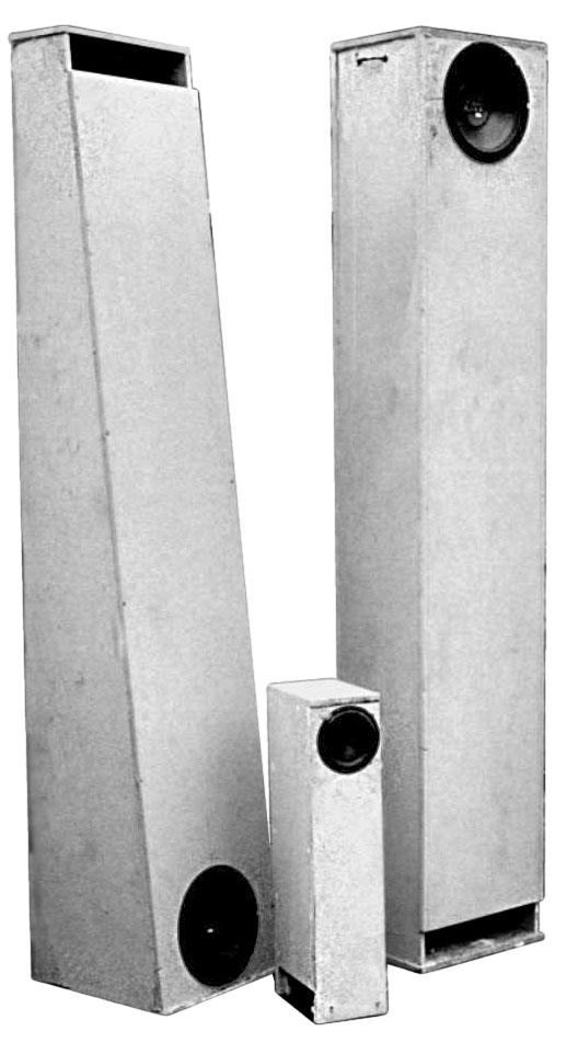
Photo 1. The eight foot tall Rhinos. Internal volume and aperture are the same for both models. Between them is a satellite that grew out of this project. Its mid-bass response seems good. It features the six and one-half inch coincidental coaxial Pyle PD65. |
||||||||||||||||||||||||||||||||||||||||||||||||||||||||||||||||||||||||||||||||||||||||||||||||||||||||||||
Cabinet length was based on fs. Length should be near one quarter of a wavelength at fs. Cabinet length for the FA124 should be 102.7 inches (13560 in/sec divided by 4fs). Because these are subwoofers and driver fs is somewhat low, the cabinets were long. For my test model, I wanted the system to be straight. Speaker building is a practical endeavor. Since a sheet of material is eight feet long, my cabinets were too. |
|||||||||||||||||||||||||||||||||||||||||||||||||||||||||||||||||||||||||||||||||||||||||||||||||||||||||||||
My next concern was aperture. My cabinet design used Thiele-Small parameters to predict optimal aperture. Aperture (Sa) for the FA124 was 65.4 in2. Optimal volume was also derived from Thiele-Small parameters. For the Pyle FA124, volume (Ve ) was 19,996 in3. These three length, volume and aperture are the most important cabinet dimensions. Aperture times length was a smaller volume than the 19,996 in3 needed. Aperture was independent of driver area and was independent of length and volume. For these design criteria to come together the cross-section was larger than aperture. Schematically, the side view of the test cylinder appears in Figure 1. Dimensions are inner measurements. In Photo 1, you can see my cylindrical test model had a rectangular cross-section. I had two test models; the other was conical. Length, volume and aperture were the same for both. Taper of the conical system was not arbitrary. The ratio of base area (Sb) and top area (So) was 2.54 for my test model. Figure 2 is the side view for the cone. I used 5/8" particleboard. I did not use any internal bracing for the test cabinets. The large, unbraced panels undoubtedly generated some unwanted sound. The cabinets were completely airtight. If the cabinets were not airtight, I could feel air moving out of the defect and could hear turbulent whistling. (To experience this, you can drill a small hole anywhere in the cabinet but fill it afterward.) I used Liquid Nails the entire length of each joint. I made sure the bead of adhesive was continuous. I screwed the top and bottom to the back, then attached the sides. Some quick work was needed to get the sides in place. I tightened them snugly. I could see material ooze out and fill the gaps. Another place I checked for leaks was around the driver. A gasket is provided with the FA124 and it worked well. I used drywall screws to hold the cabinet together. The adhesive set up over night. I left the screws in for additional security. |
Figure 1 (left). Schematic side view of Rhino cylinder. Figure 2. Schematic side view of Rhino tapered cone. |
||||||||||||||||||||||||||||||||||||||||||||||||||||||||||||||||||||||||||||||||||||||||||||||||||||||||||||
| For my personal use, I
shortened the system and combined two systems into one enclosure. I shortened them
to reduce mid-bass ripple. I did not fold them. I used diagonal braces for the walls.
I did not use braces near the aperture because they may effect airflow. I installed
dowels to stabilize the panels near the aperture. I also installed a cross brace
behind the FA124 magnet to mass-load the motor. Three long screws mass-load the cabinet
to the house. Before I took them for testing, I had to try them out. The cabinets were lying on the basement floor. I used my 200 watt/ch Adcom GFA-1 amp; its old but wonderful. With the subharmonic setting at one-third and volume at one-third, my whole two-story house moved. The more sonic energy I got in the lowest octave, the easier it was on my amp. High efficiency is like free amplifier power to me. Cone printing got blurry but rarely made wild jumps. Cone motion was reasonable. I felt confident in the design. Subjectively, they had the expected tight and powerful sound quarter-wave systems are meant to produce. Output was enveloping. I believed they were a bit warm. Once built, I drove the test models 90 miles to Madisound for testing. Aperture output is shown in Figure 4. Driver output is displayed in Figure 3. These are frequency response graphs. Several important features are identified. Some of my terminology is new so a glossary follows Figure 3. |
|||||||||||||||||||||||||||||||||||||||||||||||||||||||||||||||||||||||||||||||||||||||||||||||||||||||||||||
|
Comparison of driver output from Rhino cylinder and cone. There is a dramatic null at fn. Although fQ is set according to fs (33 Hz), the null is shifted down near 25 Hz. The 3Q lift is expected at 106 Hz but has shifted down near 90 Hz |
Comparison of aperture output from Rhino cylinder and cone. Cone response improves 3dB from 30 Hz to 80 Hz. Peaks and troughs beyond 70 Hz are the "wrinkles" of the Rhinos. They can be suppressed with stuffing. |
||||||||||||||||||||||||||||||||||||||||||||||||||||||||||||||||||||||||||||||||||||||||||||||||||||||||||||
|
Driver response curves
(figure 3) show some interesting features. The most important feature is the dramatic
null at fn. The driver does not move at all here. I was astonished when I first saw
the frequency response. The material I read suggests the driver does not move at
fQ. However, driver null is 25 Hz for the cylinder and 28 Hz for the cone. That is
about one-half octave below fQ ! The byproduct of an efficient cabinet is the downward
shift of fn. Building an efficient system by selecting the best aperture and volume
moved fn. If I were building for maximum sensitivity, the null would be at fQ. (This
leads me to a question about stuffed systems: Is it the stuffing or the interaction
of driver and enclosure that lowers driver null?) Aperture output has two componentsacoustic resonance and quarter-wave resonance. Quarter-wave resonance is related to length from aperture to closed end. I label it fQ. Because the system is 96 inches long, fQ should occur near 35.3 Hz. Acoustic resonance is related to other cabinet dimensions. I label this fe . When designing for maximum efficiency, it is this acoustic output which needs to be accentuated. Efficiently designed quarter-wave systems have aperture output below fQ. My quarter-wave system predicts substantial output to 17.4 Hz for the FA124. The tests ran down to 20Hz. There is an aperture null near 3Q. Leaving the system unstuffed has a terrible cost. Beyond 3Q, aperture output has wild and unpredictable undulations into midrange. These are the extra, undesirable "wrinkles" of the Rhinos. It is clear mid-bass output from the aperture must be suppressed. The best quarter-wave enclosures attenuate mid-bass at least 18dB above 120 Hz. Clearly, both test models have too much aperture output above 120 Hz. There are a few ways to attenuate aperture mid-bass output. You may crossover near 3Q . Polyester or wool stuffing attenuates mid and high frequencies while very low frequencies are only slightly effected. I lightly stuffed the cabinets I build for home use. It is also possible to build a fifth order system with limited mid-bass output. Both Rhinos work great as subwoofers. Total cylinder output +/-1.5dB from 21 to 85 Hz and +/-3.0dB from 18 Hz to 155 Hz. They cover the bottom 2 octaves extremely well. Unfortunately, these two designs suffer some ripple beyond 80 Hz. You may consider crossing-over at 80 Hz to attenuate the irregularities. If you are willing to tolerate a little ripple, they can be crossed over as high as 110 Hz. That is over 2 _ octaves. The cabinets are a bit big for an apartment dweller but I can use them in my house. I have pointed out some interesting features of the systems. Objective tests confirm and explain my subjective observations. |
|||||||||||||||||||||||||||||||||||||||||||||||||||||||||||||||||||||||||||||||||||||||||||||||||||||||||||||
|
|
|||||||||||||||||||||||||||||||||||||||||||||||||||||||||||||||||||||||||||||||||||||||||||||||||||||||||||||
|
Knowing how Sa, Ve and fe interact allows some predictions. Good drivers are hard to find. When building for low frequency efficiency, good drivers have a product of fs and Qts between 33.6 to 134.4. These drivers have fe between 20 and 40 Hz. If you are willing to generate some subsonic output, fsQts product can be as low as 24.5 for fe down to 17 Hz. Good drivers also have relatively low Vas. Combining high Qts and low Vas allows smaller cabinet volume. Table 1 contains the best drivers I have found. I have a spreadsheet with 224 woofers from 18 manufacturers. I considered 3-inch to 18-inch drivers. There were over 200 others I did not list because Qts was very low. I found only 15 worthwhile. Efficient systems cannot be built with low Qts, low fs drivers. Some quarter-wave designs have incorporated drivers with fsQts product below 24. They are often labeled "inefficient". This is unwarranted. In a system designed for maximum efficiency, these drivers actually have substantial subsonic output. They are not "inefficient". Instead, output is inaudible. For these drivers, fe can be moved into the audible range by changing the cabinet. Enlarging aperture (Sa) and reducing volume (Ve ) raises fe . Another benefit is a flatter impedance curve. This change moves away from maximum efficiency toward maximum sensitivity. Unfortunately, the trade-off is substantially reduced efficiency. There is less energy at the higher fe. Sa and Ve interact with the driver to form a low pass and a high pass. I set the low pass at fe and the high pass at fe . The coincidence of low pass, high pass and fe means the system is critically damped. Compression horns cover several octaves. Their low pass and high pass are far apart. They are severely under-damped. Because the Rhinos low pass and high pass coincide, efficiency improves further. These two pass filters have significant implications. Both high pass and low pass are second-order. This is different from a bass reflex design. Bass reflex systems have a third-order high pass. Duct output from a bass reflex is 270o out of phase with the back of the driver. It is 90o out of phase with the front of the driver. Duct and driver interfere below fb. At low frequencies, quarter-wave systems aperture output is 180o out of phase with the rear of the driver. Output is exactly in phase with driver front output. Aperture and driver mutually reinforce above and below fe . Mutual reinforcement is one more boost to efficiency. Compression horns require mouth area whose circumference is one wavelength. Large mouth area is needed to release the compression wave into the surrounding air. If mouth area is to small, low frequency energy is reflected back to the driver. It is never heard. This is analogous to the spring compression wave bouncing off the mass and reflecting back up the spring. Mouth area, as such, is not a concern in quarter-wave systems. There is no sound to "release". Compression horns have a confined space behind the driver and opposite the horn. In essence, this back volume raises driver Qts. Increased Qts allows larger throat area and effects bandwidth in compression horns. Quarter-wave systems have no back volume. Said another way, back volume is infinite. Driver Qts in unaltered in unstuffed systems. Horn taper has two components -- curvature and flare. Curvature describes a horns profile, be it hyperbolic, exponential or conical. Flare describes how quickly a horn expands. Compression horns must be exponential or slightly hyperbolic. This group of curvatures is called cosh horns. My system predicts the best curvature and flare for a quarter-wave system. Considering their relatively short length, the curvature of a quarter-wave system is very close to conical. The best curvatures for oscillation horns are sinh horns. I set out to build an enclosure with the most low frequency output possible and hoped to minimize mid-bass peaks and troughs. The Rhino cylinder and cone are very efficient. The tapered Rhino has twice the efficiency of the cylinder from 30 to 85 Hz. Output in the lowest two and one-half octaves is very flat. Another benefit is lower driver null. The cost of maximum low frequency output is mid-bass ripple. Unfortunately, mid-bass ripple remains a concern. There is room for improvement. Designing for maximum sensitivity and shortening cabinet length will flatten the ripple while it also flattens impedance. Aperture output in the mid-bass needs to be attenuated with stuffing or by crossover. Ripple and inefficiency have plagued quarter-wave enclosures. Thiele-Small parameters guide my calculation of cabinet volume and aperture. These influence taper. Optimizing aperture, volume and taper improves efficiency and helps control mid-bass. Acknowledgments: Thanks to Ted Hendricks and Dennis Crosson of Pyle Industries for technical information. Thanks to Madisound for independent testing. Thanks to Daniel Mapes-Roirdan for his article and the article by Marshall Leach. Thanks to the Designer for our world. |
|||||||||||||||||||||||||||||||||||||||||||||||||||||||||||||||||||||||||||||||||||||||||||||||||||||||||||||
|
Table 1 Efficient Quarter-wave Drivers
|
|||||||||||||||||||||||||||||||||||||||||||||||||||||||||||||||||||||||||||||||||||||||||||||||||||||||||||||
|
[ Projects | Intro | Rhinos | Exolinear Design | Jordan EXL | 40-1354 EXL ] |
|||||||||||||||||||||||||||||||||||||||||||||||||||||||||||||||||||||||||||||||||||||||||||||||||||||||||||||
