|
Constant Voltage
Speaker Measurement Circuit
by Jorge Omar
30-april-12
- Introduction
The measurement of speaker impedance
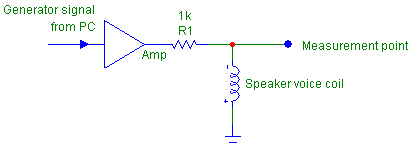
by the hobbyist is done through the constant current method -- a high value resistor
is placed in series with a voltage source (amp) and the speaker is connected from
the resistor to ground.

Figure 1: Constant current measurement
Measuring the voltage across the speaker's terminal one find the speaker's impedance.
The handicap of this method
is that just a few milliwatts of power are applied to the voice coil.
The method used by most manufacturers
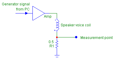
is the constant voltage method -- a small value resistor is placed in series with
the speaker, a (typically) 2.83V source (amp) drives the combo and one measures the
voltage across the resistor.

Figure 2: Constant voltage measurement
This method is deemed much more
precise to determine T/S parameters than the constant current one.
It just happens that the impedance
curve obtained by this method is upside down (higher impedance = lower voltage) and,
depending on the value of the resistor, may be significantly non-linear and one must
apply correction factors to the measurement.
To circumvent that, I've designed
a simple circuit, using inexpensive, easy to find components (Digikey, Radio Shack)
that presents the impedance in the usual way (higher impedance = higher voltage)
and is highly linear from 4 ohms to 120 ohms (2.5% tolerance at 2 ohms, the lower
measurement limit, improving to 1% or better at higher values).
The circuit does not make use
of microprocessors -- a very clean solution -- since the typical hobbyist does not
have access to the programming devices needed to upload code to the uC.
This circuit, at the time of
this writing, was only simulated using SwitcherCad III, a very good freeware SPICE
program from Linear Technology (the chip manufacturer).
SPICE is the industry standard
simulator for analog design, and with the right models the chance that such a simple
circuit is on target, are very high.
If someone cares to do a PCB
layout for it, and post it in the NET I will build and test a real prototype.
To take measurements, besides
the circuit, one needs a PC (or a Mac) with sound card and some of the freeware audio
generators available on the NET.
- Description

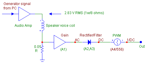
Figure 3: Block Diagram
The circuit uses two chips --
a TLE2074 (improved version of the old TL074 opamp) and a TLE556 (dual, CMOS version
of the 555 timer).

Figure 4. Circuit schematic
Two PNP transistors -- any high
gain audio will do, simm used 2N3906, are used as a current mirror.
Parallel resistor were used to avoid the need to search for harder to find values
-- (ie two 0.1 ohms in place of one 0.05 ohms resistor).
The speaker current is sampled
through R20 and R21, amplified by A1, rectified
and filtered by the combination of A2 and A3, where it becomes
a very low ripple DC.
The 2 poles switch (Swa,
Swb) increase the integration time of A3 and shall be open for measurements
from 50Hz up, the fast mode.
To measure from 50Hz (or about)
down, such as a subwoofer driver, the switch shall be closed to avoid excess ripple
on the DC; the measurement time, however, will be much longer -- some 5 sec per point.
From the output of A4,
the voltage goes to A4, that in conjunction with Q1 and Q2
(current mirror) controls the charging speed of C13, the timing capacitor
for monostable T2.
T2 is triggered by
the output of T1, connected as an astable multivibrator.
At the output of T2
we have a PWM wave between 0 and 12V, inversely proportional to the DC voltage applied
to A4.
This PWM voltage is stepped
down by R10, R16 and P1 and filtered by C15,
so that there will be a DC of 10mV/ ohms of speaker impedance.
This way, a 2 ohms (lower limit)
impedance will read as 20mV and 128 ohms (upper limit) impedance will read 1.28V.
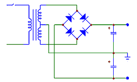
The circuit is feed from regulators
of the 78/79XX family, with the current mirror transistors feed from 15V and the
chips from +/- 12V due to the 3.3V Zener diode D1.

Figure 5: Power supply schematic
- Calibration and usage
- Without anything connected
to the circuit, just powered up, measure the voltage at the Cal testpoint (output
of A3)
- If there are more than some
5mV, reduce this offset value by experimenting with resistors (220K a good starting
point) from testpoint Z (junction of R22/R23) to +v if there
is a negative voltage or to --v if there is a positive voltage until the voltage
at Cal is as close to zero as you care to go (I did it this way to save a trimpot
-- you can opt to place a 100K pot between +v and --v and a 100K resistor at the
slide and have a nice, easy adjustment).
- Connect the amplifier to the
sound card output and adjust the audio generator program for 100Hz (really not critical).
- Connect Amp ground in the circuit
to the amplifier ground.
- Measure the value of an 8.2
ohms (5W or more) and connect it in place of the speaker (one side to the amp live,
the other to Speaker in of the circuit).
- Place a voltmeter at the Cal
point (output of A3)
- Slowly increase
the amp volume (or the audio generator output, if the amp does not have a volume
control) until the voltage at Cal reaches 2.5V.
- Place the voltmeter at the
output and adjust P1 until the reading is (the value you measured for
the 8.2 ohms resistor) times 10mV (say you measured 8.4 ohms --
adjust for 84mV)
- Check linearity by replacing
the 8.2 ohms resistor by a 120 ohms one (measure it's value, also). The output voltage
shall be very close to 10mV times the real value, circa 1.2V.
- If the voltage is grossly out,
you need to adjust R6 (again, if you prefer it can be a trimpot) by lowering
its value until suddenly there will be the correct value at Out.
That's it!
Now, replace the resistor by
a real speaker, and you are set for constant voltage measurement.
Do not forget to do the level
calibration (step
3-g) and output (step 3-h) every time you start a new set of measurements
and wait for the reading to stabilize before changing frequency.
Enjoy.
Note 1: the offset and
linearity adjustments do not need to be changed frequently (if ever). That's why
I did not use trimpots.
Note 2: C12
and C13 MUST be film capacitors -- not ceramic. I do not advise changing
the chips by similar types unless you know what you are doing.
Note 3: I did not do
a PCB layout for it since I've already spent lots of time running SPICE simms --
let's have more players on this team!
Special thanks to:
- Mike Engelhardt and Linear
Technology for making available such a good program as SwCAD III for free!
- Fred Bartolli (France) for
the suggestion on using the 555;
- David Dlugos for the site,
- And Dave (dbe) for the morale
support...
|


