|
|
|
Frequency Response Correction
|
||||||||||||
|
|
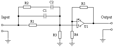
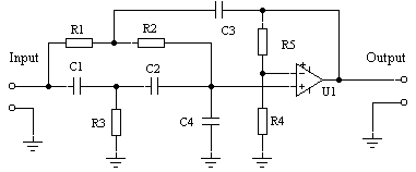
One of the nice features of the active crossovers is a simplicity of frequency response correction of the drivers used in the system. You can equalize frequency magnitudes at any point using simple RC correction circuits. Good example is a Constant Directivity (CD) Horn correction circuit. Compression drivers used with CD horns have a natural high frequency roll off at the rate of 6dB per octave. A very simple circuit can compensate this roll off without compromising the overall frequency response characteristics.
A similar approach can be used to correct frequency response at any point of the spectrum. Each driver in the system can be adjusted individually in order to compensate low sensitivity of a driver, without affecting efficiency of the other drivers in the system. All you have to do is to adjust the output potentiometer of the corresponding filter. When using passive crossover, you will need to reduce the output level of all other drivers in order to bring them down to the level of the least efficient driver, thus reducing overall efficiency of the loudspeaker system. If you need to eliminate peak at the resonance frequency of the driver or the cabinet, you can do that as easily as any other correction in a low-level signal pass. Try to reduce low-frequency driver resonance at about 40 Hz using passive crossover components and very soon you will find out that you need expensive capacitors and high-power resistors. In active crossovers, the same problem is solved with standard 1/4 W resistors and small film capacitors.
Almost any correction of the frequency response is possible when you use active crossovers and all equalization is done without using separate parametric or graphic equalizers. When design process is finished, all these correction circuits are integrated on the final edition of the crossover printed board together with filter circuits and input/output circuits. |
|||||||||||||
|
|
||||||||||||||
|
|
|
|||||||||||||
|
|

