|
|
|
State-Variable or Sallen-Key or what?
|
||||||||||||
|
|
As we mentioned before, different types of filters (or filter alignments) can be implemented using different circuits (or filter topologies). Here, we will briefly discuss the most commonly used circuits and their pluses and minuses. State-Variable filters are the most popular and are used by the majority of companies manufacturing crossovers.
Figure 1. Typical 4th order State-Variable filter circuit
This filter provides simultaneous High Pass, Low Pass and Band Pass outputs. HP and LP outputs are 4th order (24 dB/octave) and BP output is 2nd order (12 dB/octave).
The popularity of this circuit topology is overwhelming. Even non-adjustable crossovers are made using state variable circuits because low pass, high pass and even bandpass outputs produced by this circuit simultaneously and crossover points of the two adjacent passbands are always at exact frequencies. We already know, that these filters can be adjusted using multi-gang potentiometers, but cheap potentiometers do not provide enough precision and high-precision potentiometers are very expensive. Another approach to this problem was taken by some of the crossover manufacturers: use of Voltage Controlled Amplifiers (VCA) for adjustment of the crossover frequencies and other filter parameters. VCAs allow use of the single inexpensive potentiometer for adjustment of regulating voltage which drives all VCAs simultaneously, but precision of the circuit parameters still is not as high as in a case with fixed filters and Total Harmonic Distortions plus Noise (THD+N) characteristics are not very good. Sallen-Key filters are very popular as well.
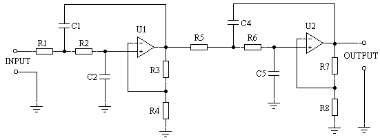
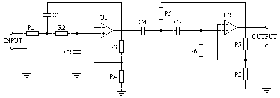
Figure 2. Sallen-Key filter circuits.
This is a 4th order (24 dB/octave) Sallen-Key low pass filter circuit. Only one OpAmp is needed for this circuit.
This is a 4th order low pass filter circuit made out of two second order filters.
This is a 2nd order band pass filter circuit.
Most of DIY projects are based on Sallen-Key circuits because calculations of the filter component values are not too complicated and much fewer OpAmps are needed for these circuits in comparison to State-Variable filters. Some of these filters may have an inclination to high frequency oscillation and it is a difficult task to fight such oscillation. Sallen-Key circuits can be used for a high pass, low pass or band pass filters. A lot of high and low frequency cutoff filters are built using Sallen-Key circuits. This is the most economical way to get rid of sub-low frequencies which can damage the driver or reduce radio frequency interference from long cable runs. All these filters use feedback loops. Most common, but seldom used in crossovers, are filters based on the buffers.
Figure 3. Buffered filter circuits
These are High Pass and Low Pass 4th order (24 db/octave) filter circuits based on buffers. Only one OpAmp is needed for such circuit. These filters do not have frequency dependent feedback loops and theoretically can be made of any order using just one OpAmp. The problem with such filters is that you have to use inductors and this is a very difficult component to deal with. For low frequencies you will have to use very large inductor values, and such inductors will be bulky and will pickup a lot of hum and noise. You can try to reduce the size of the inductors by using very thin wire, but then internal resistance of the inductors will be too high and the total Q will be very low. Inductors are unstable and their values can change with age. To avoid all these problems, we are using simulated inductors and FDNRs.
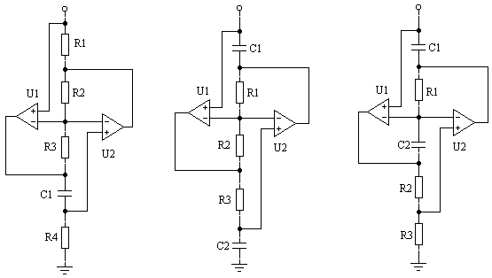
Figure 4. Generalized Impendance Converter circuits.
Gyrators: L-component and two different versions of D-components. These are Generalized Impedance Converter (GIC) or gyrator circuits. Each such circuit requires 2 OpAmps, but these OpAmps are not in a direct signal path and they are not inserting too much noise. For 2nd order filters we need only one GIC and for the 4th order filters we need two GICs.
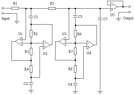
Figure 5. Buffered filter circuits based on gyrators.
High Pass 4th order filter circuit with simulated inductors.
Low Pass 4th order filter circuit with FDNRs. This is probably a good place to discuss the question of what parts are the best to use to build an active crossover. Some people would like to use vacuum tubes, but we do not think there is any advantage in using them. No one can produce any scientific evidence in support of the popular theories about superiority of sound equipment built with vacuum tubes. Still, some other people will try and convince the audience that only OpAmps built out of discrete components can be used for high quality sound equipment. Well, we are not in support of such an idea either. Back in the late 70's and early 80's, the only OpAmp available for audio applications was a classic 741 and its varieties. At that time, discrete OpAmp such as 990 was superior to the 741. Since then, large semiconductor manufacturers invested a lot of money and effort into developing better and better integrated circuits and today OpAmps have much better parameters. New technological advances in the manufacturing processes allow laser trimming of integrated components to unbelievable precision which is not possible to achieve in discrete OpAmps. Even such advanced (for its time) OpAmp as 5534, is now obsolete because new Operational Amplifiers are so much better in all their parameters. Companies, such as Burr-Brown or Analog Devices, now produces Operational Amplifiers and other integrated circuits designed specifically for high quality audio equipment and for use in active filters, or microphone preamplifiers etc. Passive components, such as resistors and capacitors, are much easier to choose for our application. Resistors are to be of 1% precision, metal film type with a low temperature coefficient of 50 ppb or better. Capacitors are polypropylene sulfide or polypropylene with 1% precision values. In critical applications, we select these parts in matching pairs with .05% precision or better. Because of relatively high signal levels, crossovers are not so sensitive to thermal noise or power supply noises. Still, we are using toroidal transformers only and multistage regulated power supplies in order to avoid any possibilities of introducing additional noises into the audio signal. Before, when all signal sources were analog only and a dynamic range of 70-80 dB was acceptable, designers were not bothering themselves with extra precautions against noise at high signal levels. These days, digital signal sources have a dynamic range of 110-120 dB and we have to be very careful in order not to reduce it. |
|||||||||||||
|
|
||||||||||||||
|
|
|
|||||||||||||
|
|


