|
DIY2000 -- Crossover Division Entry By Jeff Bagby
[ Intro BDS | BaffleStep | BaffleStep Compensation | PLLXO | Sallen-Key | XO Design | Tube XOs | DiAural ] |
|||||
| Important Post DIY2000
Comments: I am making this paper available due to all of the requests that I have received since the DIY2000 Contest. I am actually quite amazed that this crossover did as well as it did in this contest, but judging from the comments that have been made it came in a close second to Dennis Murphy’s winning design. In my opinion Dennis deserved to win, given his design approach and the fact that he built and tested his design with the speakers, making measurements and adjustments as he went. This is the way a speaker should be designed, not that way that I have done it here. However, as I have stated many times, this was the purpose of my experiment; could I use Phil’s data and design a competitive crossover using that alone? Based on these goals I would say that this crossover was an overwhelming success. However, I also want to point out that this design is not without it’s flaws, as would be expected for any crossover designed in this way. I am certain it could have been improved upon if the extra steps Dennis took were also taken here. In this paper I have simply given an overview of DIY2000 and the approach I took to this crossover design. For the beginner I have attempted to explain some things that enter into crossover design that need to be taken into consideration. This paper is actually written for just that sort of person. After the contest there was a lively discussion on Madisound Discussion Board regarding DIY2000. Rick Craig shared his frequency response measurements and how they deviated from flat response. John Kreskovsky modeled a simulation of each crossover based on imported driver data and the circuit schematics. These simulations show a step in my crossover’s response between 700Hz — 1kHz. Rick’s measurements showed the same step but not quite as exaggerated as the simulations. Although I do show a bump in this region, this step does not really appear in my simulations and I will explain why. In designing this crossover I considered whether or not I should compensate for the full baffle diffraction loss. In determining this answer I took measurements of my own 6.5" 2-ways in various positions in the room. I concluded that if the speakers were placed with a couple feet from the rear wall, which is how I perceive most people set up their speakers, I would get some room reinforcement. This reinforcement implied that I likely did not need to compensate for the full baffle step loss. Therefore, I modeled my design taking some reinforcement into consideration. However, during the contest the speakers were positioned quite far into the room and full baffle step loss was realized. This caused the —2.5 dB drop below 700 Hz that Rick measured. There was also another reason and it aggravated this condition: The Vifa PL18 woofer has a natural "bump" in it’s response centered around 700Hz. My crossover simulations show that there is still a remnant of this bump present, but it is very small. However, its presence is precisely in the region where the baffle step would begin so it exaggerates this step if the speaker is moved into the room. It is difficult to eliminate this bump with a simple circuit like I used. I had hoped my low crossover point would do the trick. I believe that if you plan to have this speaker placed within 18" of the rear wall it will measure fairly close to these simulations. If, instead you plan to position into the room, far away from boundary reinforcement then Rick’s measurements would be a true indication of the sound. Based on this I have included an alternate crossover circuit at the end of this paper that will have a flatter response in this position. In this crossover I have also eliminated the second capacitor for the tweeter because in this case I achieve better phase matching with a second order filter on the tweeter, and a deeper null was achieved as well when reversed. If anyone would like to try it they may be my guest. I feel that now, having the benefit of appraisals and measurements; it is a good time to reevaluate this design a little. I suspect, given all that has been learned since DIY2000 this alternate filter will sound better than the original. However, the original was still quite successful given its scores and placement in the DIY2000 contest. Jeff Bagby, 10/12/2000 |
|||||
|
Original Crossover Design |
|||||
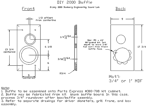
| Introduction: Originating through a discussion on Madisound’s Discussion Board regarding the sonic differences between Parallel and Series crossovers, DIY2000 was established as a means of testing those differences. Since then it was expanded to include original speaker designs as well, but this entry, and likewise this paper, will deal strictly with the crossover division of the contest. The members of the discussion group decided to take one pair of bass-mids and tweeters, mount them in a box and have each entry design a crossover for these drivers. The crossovers would then be tested and the speakers listened to with each entry, and a review panel would select the best sounding design. |
|||||
| The drivers used were
decided on by a majority of the participants in the discussion group. The drivers
selected were the Vifa PL18-08 bass-mid and the Seas Excel T25-001 tweeter. The box
selected was a Parts Express box with a modified front baffle. Phil Bamberg of Bamberg
Engineering Sound Lab constructed the cabinet and baffle for the contest. He also
produced impedance and frequency response graphs of the actual drivers used in the
contest, as well as the time delay between them, and posted this information on his
website. Participants who did not wish to purchase the drivers could download this
information and use it to simulate their designs. Other participants purchased the
drivers and built full systems before entering their crossover designs. All designs were then shipped to Rick Craig of Selah Audio where the evaluations would take place. |
Fig 1: DIY 2000 Baffle |
||||
|
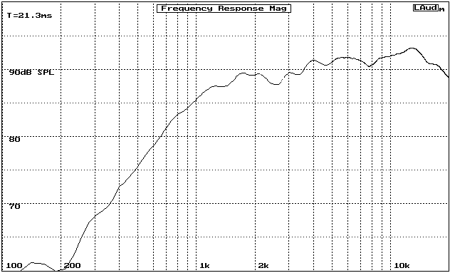
Fig 2: Phil’s frequency and impedance plots for the woofer Fig 3: Phil’s frequency and impedance plots of the tweeter Fig 4:Phil’s Laud measurements of the Tweeter. Note difference in the top octave.
|
|||||
| Design Approach: My design approach was a risky one. I opted to design a crossover without purchasing the drivers and building it first or being able to listen to it and tweak the design. I was placing a lot of faith in Phil Bamberg’s measurements and in the CALSOD software package used. However, this was a calculated risk because I knew that Phil had used a good system and the correct methods in producing the measurements of the drivers. These were also the actual drivers that would be used in the contest. I concluded that if I had purchased drivers for myself and they measured differently, and I proceeded to build a crossover based on them, then it would not sound the same when used with the contest speaker. Therefore, I felt there was some advantage to using Phil’s data, as long as the data was accurate. I put faith in the fact that it was. I am also very experienced using CALSOD (Computer Aided Loudspeaker Optimization and Design software, by Audiosoft, Melbourne, Australia) having used for several years. I am very familiar with its strengths and weaknesses and felt that using Phil’s data I could arrive at decent results using this CAD program. Of course there are obvious disadvantages to building a crossover and sending it in to a design contest having never heard it played with the drivers. I would normally never recommend anyone do it this way. However, this was part of my experiment; could a person design a crossover based on certain known information and a specific design approach and have it perform well enough to be competitive? I guess I will find out. What follows is an explanation and breakdown of my crossover design and how I arrived at it. |
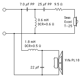
Fig 5: Original contest crossover schematic: |
||||
|
Concept and Objectives:
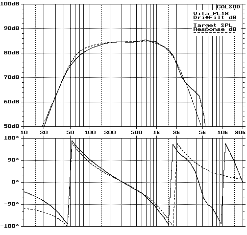
Fig 6: Predicted acoustic responses vs target L-R responses |
|||||
|
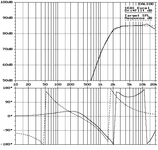
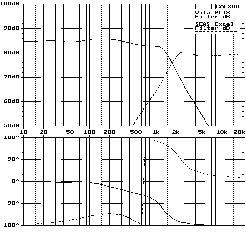
Description of Final Design: I modeled Phil’s frequency and impedance measurements in CALSOD as closely as possible, but I also used 1/3 octave smoothing of the frequency response since it is difficult for the crossover to correct deviations any smaller than this. Target sensitivity was set at 85 dB/2.83V/M. this allows for nearly full baffle step loss compensation. On the lowpass I originally began with a 2nd order filter with a Zobel, but through optimization I was able to reduce the circuit to a simple overdamped 2nd order filter without any impedance compensation. The fairly large Inductor value of 1.80 mH provides the exact compensation for the estimated partial baffle step loss. When shunted by the 22uF capacitor, and operating into the natural impedance of the driver, this simple circuit gives a near textbook 4th order L-R lowpass acoustic response at 1.75 kHz when the driver’s natural frequency response is included. This can be seen from the attached graph that the acoustic response follows the L-R target response all the way to 3 kHz where it deviates due to peaking in the driver’s response. The peak at 4 kHz is still down 20 dB at this point. My design goal of producing the simplest circuit possible to achieve a 4th order L-R response with baffle step compensation was a success since this circuit used only two elements. Now to do the same thing with the tweeter’s high pass section I needed to employ a crossover technique that is not often discussed but is highly effective. Although flat frequency response around the crossover point could be obtained using a second order filter on the high pass section as well, it is not possible to get good phase matching because of the 24mm off-set of the acoustic centers. However, if the high pass circuit is increased to a 3rd order electrical filter and optimized it is possible to match the relative acoustic phase of the woofer and tweeter down to very low frequencies. This phase matching demonstrates that a true acoustic L-R transfer function has been obtained despite the driver offset. The reason this is possible is because a higher order on the high pass circuit has a greater group delay and phase shift than the 2nd order low pass circuit has. If the crossover frequency is carefully selected with regard to the offset distance then the higher order high-pass filter can be made to fully compensate for this offset and provide near perfect phase tracking. (Note: this is not the same thing as a minimum phase crossover, which are extremely difficult to achieve. Also, it is not "time aligned" either, it is simply an in-phase crossover, meaning that both drivers are in the same relative phase to each other).
|
|||||
|
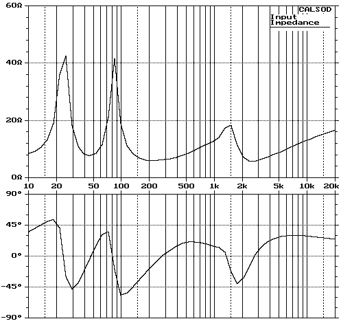
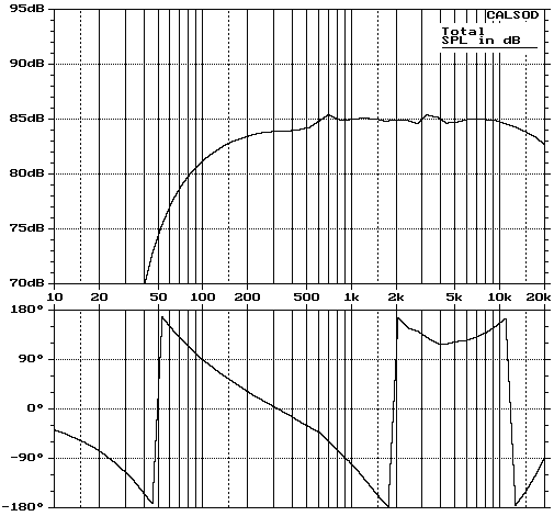
The 25uF capacitor in the high pass filter is not necessary if the only goal is what occurs in the immediate crossover range, flat response is obtained without it. However, this capacitor is used for two purposes; to provide better relative phase tracking with the woofer, and to provide more protection from low frequencies since such a low crossover point is used. What is the purpose of this phase tracking if it is not necessary to for flat summed response? Well, by maintaining this relationship through the passband lobing in the vertical polar response is more ideal. Although this may or may not be important, it is still easy enough to achieve. You will note from the attached graph that the tweeter and filter’s combined acoustic response matches the target 4th L-R response extremely well. In a 4th order L-R crossover both drivers must be in phase at the crossover point. Because of this both drivers will need to be down 6dB at the crossover point in order to sum to a flat response. There is a graph provided that shows the predicted transfer functions of the crossover circuits as approximated into both speakers’ natural impedance. Also provided are simulations of the total system impedance and the summed frequency response. You will note from this graph that the tweeter’s phase tracks with the woofer’s very precisely from approximately 200 Hz to about 4kHz. It is not possible (using a conventional crossover) to force the tweeter’s phase to track with woofers beyond these frequency points. The reason is because the phase deviations beyond these points are to due entirely to the woofers response curve. The phase shifts below 200 Hz are due to the low frequency response tuning of the woofer and box, and the phase shift above 4 kHz is caused by the rapid roll-off of the woofer above this point.
|
|||||
|
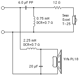
One final note on integrating these two drivers using a simulation: Phil’s original data on the tweeter showed the upper octave to be quite rolled off. In response to this he made another set of measurements using LAUD that showed the response to be much more extended with a slight peak around 13Khz. The level also differed between these two plots by about 1 dB. Not much, but when you are trying to level match a woofer and a tweeter using separate graphs and you have different plots for the tweeter, you are really guessing at which to use. I decided that the tweeter’s response was likely to be better represented by the LAUD measurement that shows it more extended. However, if there is any area where my simulation may really miss the mark it may be in matching up the levels of the woofer and tweeter. We will have to see. Most small speakers use a flat baffle that naturally includes a front to back offset delay between the woofer and tweeter. I have found that this is almost always correctable using asymmetrical or mixed slope crossovers (referring to the electrical slopes and not the final acoustic slope), due to the extra phase shift in the higher order high pass section. I have come to refer to this type of crossover as the Asymmetrical Quasi 4th Order Linkwitz — Riley Crossover. This is a crossover topology that I have used many times over the past six years and I have found it to be very repeatable in obtaining good results. Part of my experiment here was to see if using these principles I could design a crossover that provided good results even though I could not listen to the system or tweak the results as I normally would. Naturally I would not expect this crossover to be as good as if I made it, then listened and made adjustments to it, but that is simply part of the test. Sketch of Circuit and Values: The low pass section of this parallel crossover would be described as a simple 2nd order low pass circuit made up of a 1.80 A.C. mH coil (DCR 0.5 ohm) and a 22 uF capacitor (made up of several smaller mylar caps combined). No zobel was used to compensate for the impedance rise since the optimizer worked better without it. The high pass section would be described as a simple 3rd order high pass circuit consisting of a 7.0 uF polypropylene capacitor, shunted with a 0.60 A.C. mH coil (DCR 0.5 ohm), and then another polypropylene capacitor of 25 uF. Finally there is a resistor of 9.5 ohms made up of a 20 watt 8 ohm non-inductive resistor in series with a 15 watt 1.5 ohm resistor. (A simple 10 ohm resistor would probably work just as well if this design is repeated). |
|||||
|
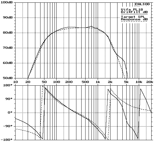
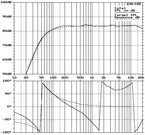
Addendum This is a post DIY2000 computer refinement based on measurements and other simulations using full baffle step that was experience during the contest. Based upon the feedback I felt it was possible to improve on this design. Since I was able to model Rick’s measurements very closely by simply adding the full baffle step loss I felt a computer refinement would be valid. With full baffle diffraction loss and original tweeter response modeled the prediction is very close to John Kreskovky’s simulations and Rick Craig’s measurements. This clearly shows the step beginning at 500 Hz and the pronounced bump at 700 Hz. It also shows the original roll-off of the tweeter’s response. Using this curve as a baseline I went back to the crossover to redesign it for flat response with the full baffle step included. This time I found that by using the larger inductor on the lowpass, which spreads the crossover’s resonant frequencies a little further apart, I could achieve much better phase matching using a second order circuit on the high pass.
|
|||||
|
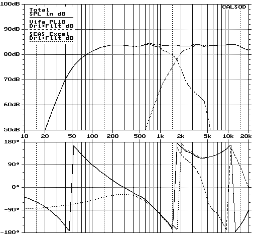
I still maintained the 4th order L-R response and kept the crossover point at the original 1.75kHz. After hearing the response from people who attended DIY2000, and reviewing Rick Craig’s measurements and John K’s simulation (which I could essentially match), I feel that this newly designed alternate circuit should be superior to the original second place design. Of course, it has not been built and tested, but actual measurements of the speaker with the original crossover would indicate that this should be the case. I welcome feedback or comments from anyone who may desire to build this speaker and try this crossover. I would love to hear what you think. Below you will find graphs of the newly optimized predicted lowpass acoustic response, the predicted summed response, and the summed response with both drivers shown. Finally, at the end you will find the schematic for the newly revised alternate crossover.
|
|||||
|
|
|||||
| Notice the excellent phase
tracking between the woofer and the tweeter. This indicates that an acoustic Linkwitz
—Riley crossover has been obtained using this simple circuit. Also the predicted
null with a reverse polarity hook up is much deeper now than it was with the original
crossover. I played around with an L-Pad in order to flatten the impedance a little. However, when I got enough attenuation my low impedance point was a little lower than I wanted after I optimized. If I attempted to raise the minimum a little I was back to using a relatively high resistor in the series R position. Based on this I decided to go back to the single series resistor and forget the L-Pad, and just live with the rising impedance in the high frequency range. You will also notice that there is still a small bump in the response at about 700 Hz. This bump is inherent in the woofer’s natural response and to eliminate it entirely would require a much more complex circuit. I chose not to go that route, believing that this small bump would not be enough to cause any real audible concerns given it’s current magnitude. |
Fig 15: Predicted summed
response showing |
||||
|
[ BaffleStep | BaffleStep Compensation | PLLXO | Sallen-Key | XO Design | Tube XOs | DiAural ]
|
|||||
