| A Bipolar Transmission
Line Project -- the TLB
Section 6 Construction Details |
||
| The TLB construction
consists of two modules: the TL column and the tweeter module. They are separate
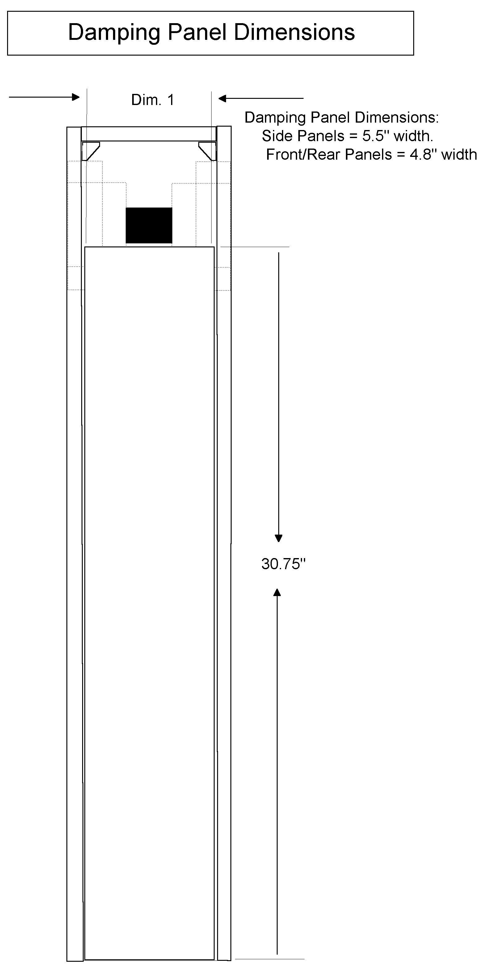
since the tweeter is time aligned to the cone of the woofer. The main case is a double
panel construction. Interior panels are 0.25" thick free floating on a 'liquid
nails adhesive' layer. This method is used to dampen the low frequency side-wall
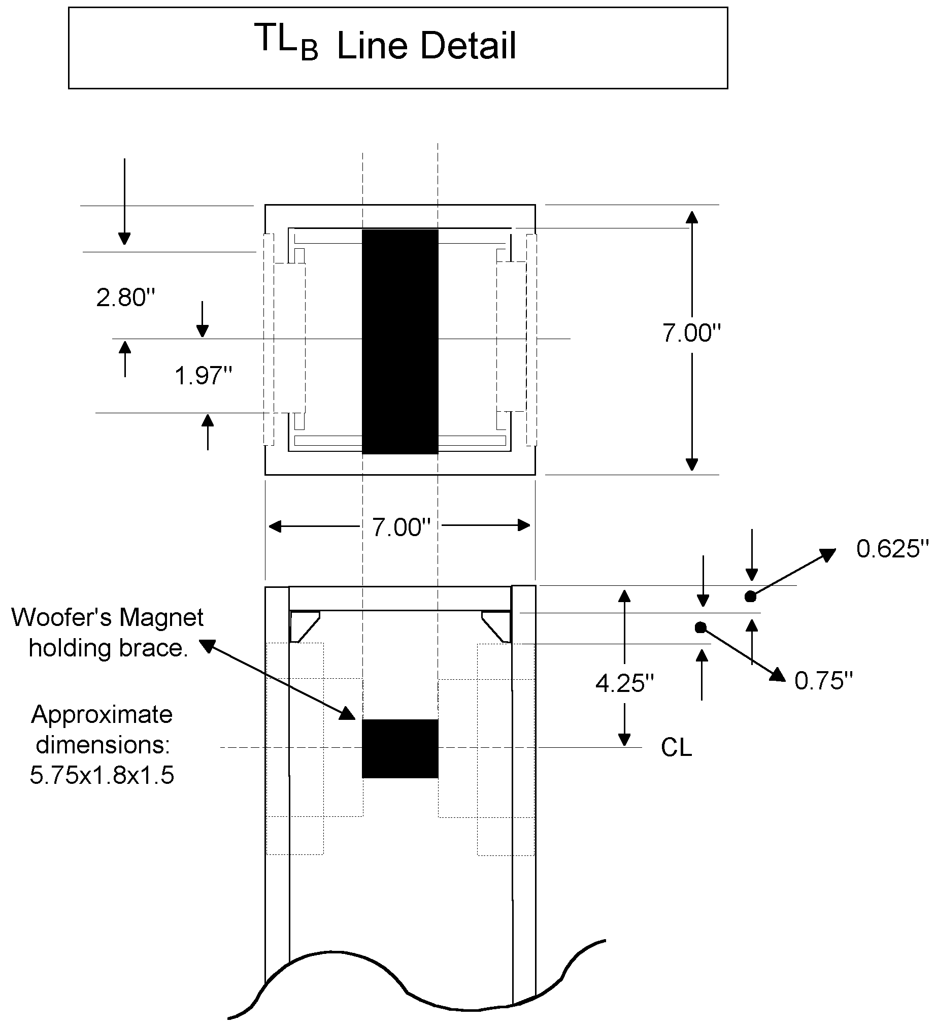
vibration. The woofer mounting technique is a Lars Mittigen innovation; the woofers
are supported by the magnet structure, ie the greatest mass of the woofer which is
coupled to the case wall. This is used to dampen the basket vibrations and the subsequent
cone coloration. This construction requires a certain amount of precision and while
described is a trial and error procedure. If you are uncomfortable in attempting
this you may use the conventional rim mounting procedure. Make sure that you have attached the driver's electrical leads before attempting the next step. click image for larger plans with dimensions |
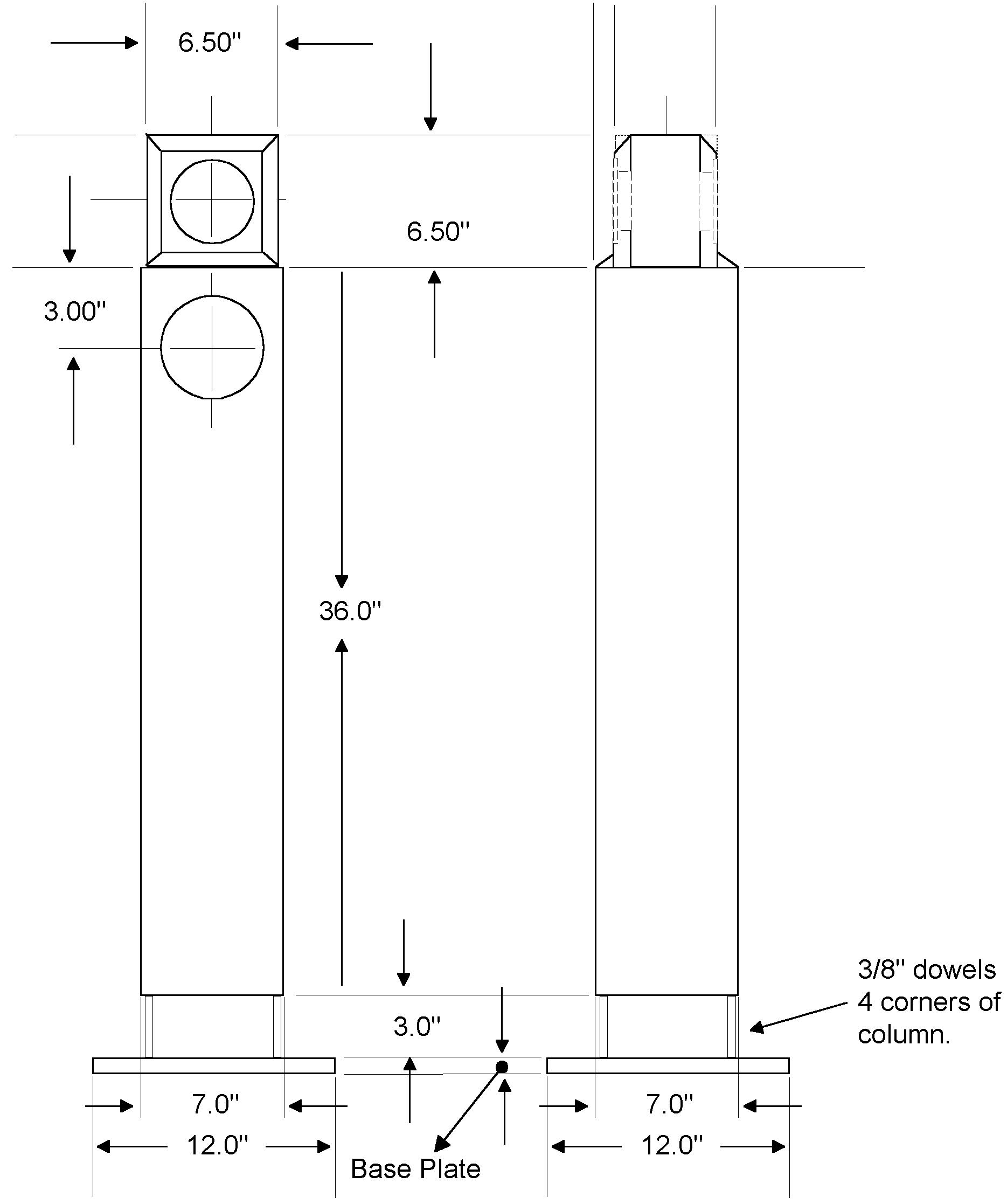
Fig. 6.0 TLB Dimensions |
|
|
It is assumed that you can work out the general panel cutting dimensions from the given data and that only the unusual steps have to be detailed. I would highly recommend using biscuits for panel construction since this would allow a dry fit before the final glue-up. However dry wall screws can be substituted. After the MDF has been cut and the dry fit verified, glue up the column leaving one side and the top not glued. Next secure all the damping panels using a liberal amount of 'liquid nails' the sub-floor variety which remains elastic. Next secure the open side with screws and proceed to the step of fitting the drivers and the magnet brace detailed on the next page. Once the dimensions of the magnet brace have been set, it is time to commit yourself. I would recommend that you remove the loose side and install the wool stuffing up to the brace line leaving a hand full for the very top. This will allow you an easy way to distribute the fiber so that it is homogenous. Once the fiber is in place glue the lose side of the column, but make sure that the top plate is loose. Now you need to epoxy the brace to the sidewalls and proceed with the driver mounting as detailed on the next page. After you have finished the driver installation fish the driver wires through the top plate and seal the wires to the top plate. Using some of the latex gasket material secure the top plate using screws. Make sure that there are no air leaks around the plate and especially where the wires exit the top plate, since this will destroy the TL's terminus gain. Next install and wire up the tweeter module. Next make the base
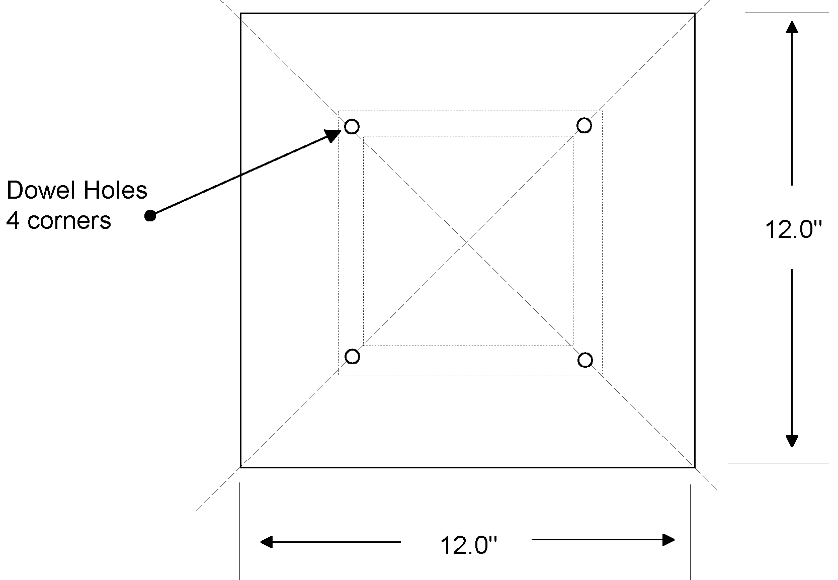
plate and using it as a template drill the holes for the 3/8" dowels that form
the legs and the TL Terminus opening. |
Fig. 6.1 Damping Panels |
|
| The Push-Push woofer mounting detail, for the column top | ||
|
Fig. 6.2 Magnet Brace Details |
It is not possible to give precise dimensions for the brace to which the magnet base is secured, since the case as well as the flush mounting depth will vary. The dimension given in the drawing of 5.75x1.8x1.5 assumes that the column interior is 5.75" and that the space between the magnets is about 1.77", thus both dimensions will have to be adjusted to reflect the actual construction dimensions. The procedure should be as follows:
After the epoxy has set apply an additional bead on the top to secure the structure. The concept is to have the woofers coupled to each other and mounted by the mass of the magnet structure to minimize any induced vibration in the baskets. Note that the caulking bead has to provide an air tight seal around the driver. Leakage will destroy the TL's terminus gain.
|
|
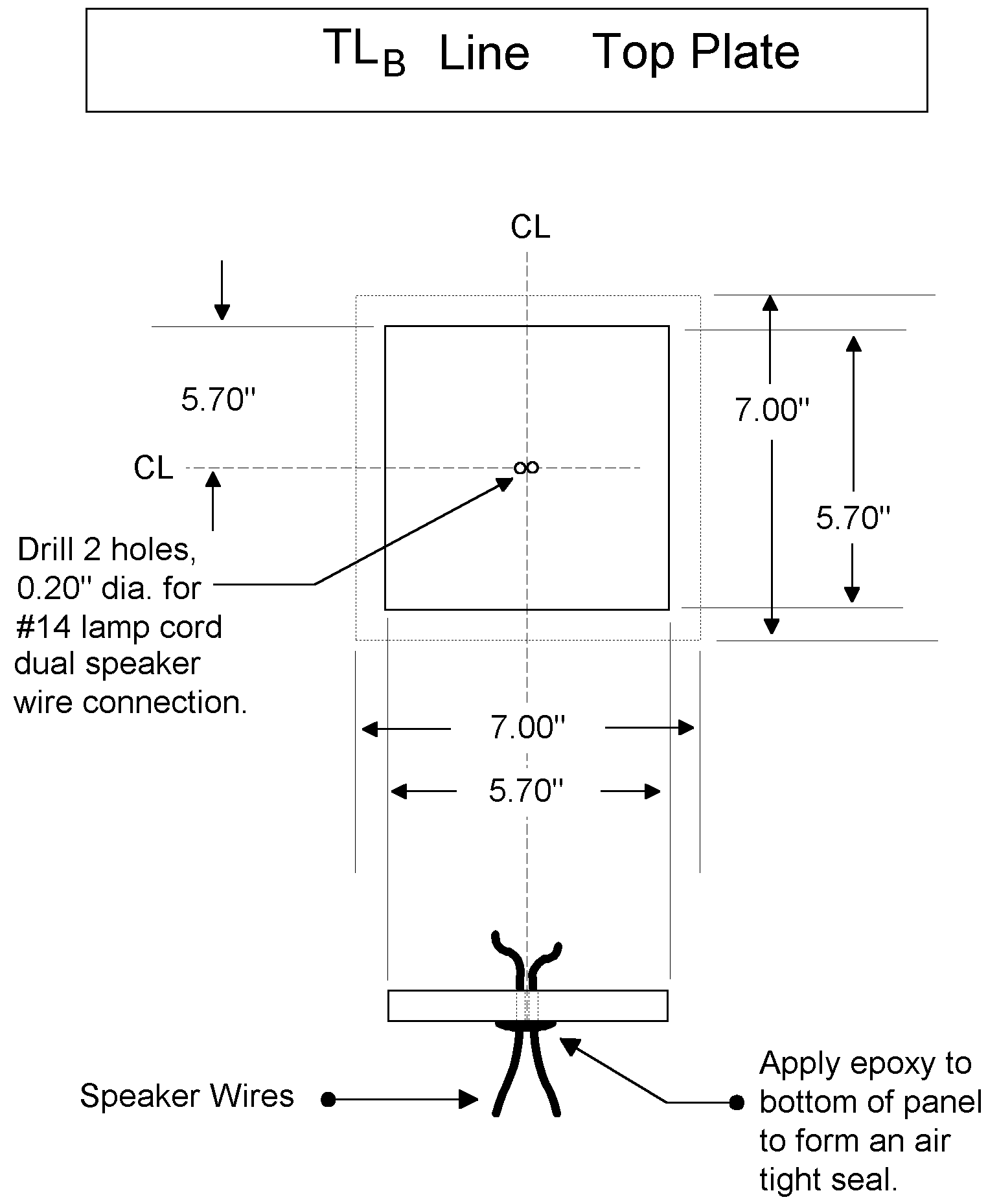
| Detail of TL column
Top Plate Two holes are drilled in the top plate for the connecting wires to the woofer drivers. Make sure that the wires are long enough and securely epoxied to the bottom of the plate and form an airtight seal The two wires form a parallel connection to the terminals of the Tweeter Case assembly. The top plate is screwed to the TL column allowing future access to the drivers. Again the top plate must have an air tight seal. |
Fig. 6.3 Column Top Plate Details |
|
|
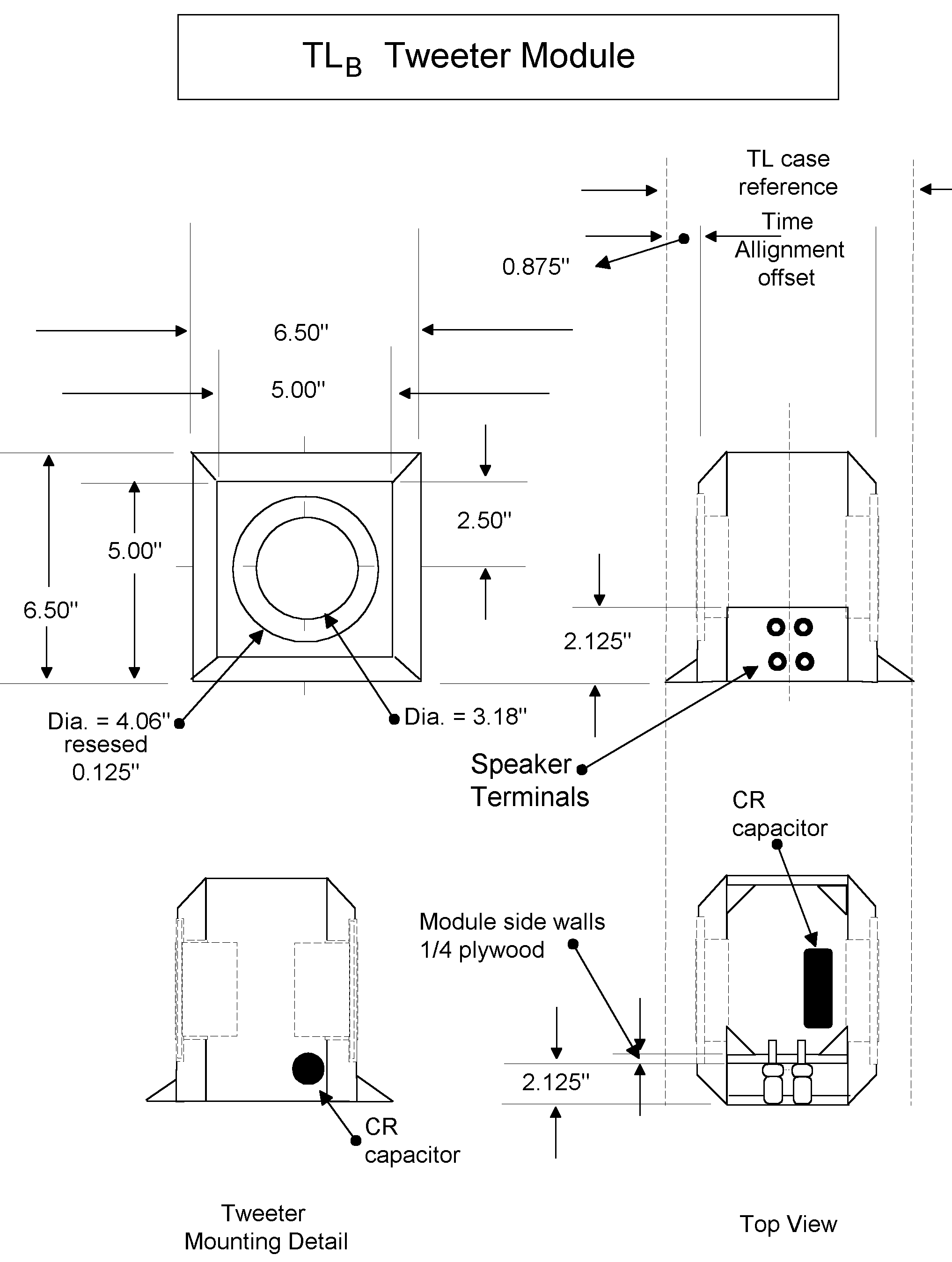
Fig. 6.4 Tweeter Module |
The Tweeter module
is build as a separate assembly containing the two Vifa D27TG-45-06 1" soft
dome drivers and the blocking capacitor Two sets of speaker terminals are mounted
in a recessed side panel, allowing the option of biamping the speaker.
Fig. 6.5 Base Plate |
|
|
Base Plate Detail A critical construction detail is the alignment of the dowels that support the TL column with the base-plate. An easy way to accomplish this is :
The base can be made from 0.75" plywood and a 0.25" plate glued to the bottom forming a base for the dowels supporting the TL case, with the edges hardwood glued and lightly beveled. The whole painted a high gloss black. A luxurious and functional option is a marble base about 1" thick. |
||
|
[ Contents | Introduction | Methodology | Radiation Response | Transient Response | Frequency Response | Construction ]
|
||