| A Phase Linear Transmission
Line Project |
|
| Section 5: Diffraction Step
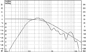
Compensation Figure 5.1 shows a NF measurement of the JX150 driver with a 500 Hz electrical filter and the 1st order target function. The match is not very good. |
|
|
Figure 5.1. Uncompensated driver
|
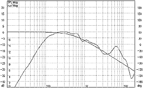
Figure 5.2. Response with compensation
|
| Diffraction step causes
a rise of 6 dB/octave from around 200-500 Hz. These frequencies depend of the baffle
width, in our case 35 cm. By setting the crossover frequency down to 180 Hz (Figure 5.2), we get very close to the target. If a higher crossover frequency is desired, the baffle width could be decreased and a higher electrical crossover frequency must be chosen. |
|
|
[ Contents | Intro | Measurements | Optimization | Integration | Step Compensation | Time Align | Crossover | Construction ]
|
|

